
Page 777 - Automotive Engineering Powertrain Chassis System and Vehicle Body
P. 777
CHAP TER 2 3. 1 Automotive instrumentation and telematics
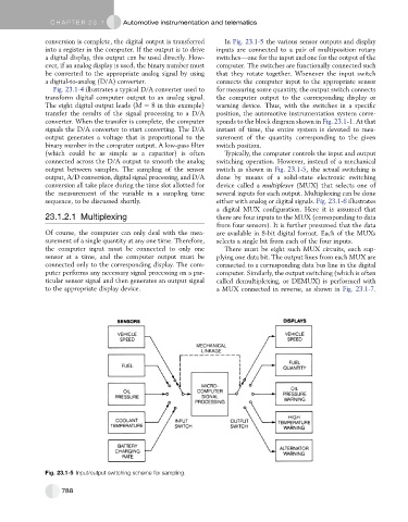
conversion is complete, the digital output is transferred In Fig. 23.1-5 the various sensor outputs and display
into a register in the computer. If the output is to drive inputs are connected to a pair of multiposition rotary
a digital display, this output can be used directly. How- switchesdone for the input and one for the output of the
ever, if an analog display is used, the binary number must computer. The switches are functionally connected such
be converted to the appropriate analog signal by using that they rotate together. Whenever the input switch
a digital-to-analog (D/A) converter. connects the computer input to the appropriate sensor
Fig. 23.1-4 illustrates a typical D/A converter used to for measuring some quantity, the output switch connects
transform digital computer output to an analog signal. the computer output to the corresponding display or
The eight digital output leads (M ¼ 8 in this example) warning device. Thus, with the switches in a specific
transfer the results of the signal processing to a D/A position, the automotive instrumentation system corre-
converter. When the transfer is complete, the computer sponds to the block diagram shown in Fig. 23.1-1. At that
signals the D/A converter to start converting. The D/A instant of time, the entire system is devoted to mea-
output generates a voltage that is proportional to the surement of the quantity corresponding to the given
binary number in the computer output. A low-pass filter switch position.
(which could be as simple as a capacitor) is often Typically, the computer controls the input and output
connected across the D/A output to smooth the analog switching operation. However, instead of a mechanical
output between samples. The sampling of the sensor switch as shown in Fig. 23.1-5, the actual switching is
output, A/D conversion, digital signal processing, and D/A done by means of a solid-state electronic switching
conversion all take place during the time slot allotted for device called a multiplexer (MUX) that selects one of
the measurement of the variable in a sampling time several inputs for each output. Multiplexing can be done
sequence, to be discussed shortly. either with analog or digital signals. Fig. 23.1-6 illustrates
a digital MUX configuration. Here it is assumed that
23.1.2.1 Multiplexing there are four inputs to the MUX (corresponding to data
from four sensors). It is further presumed that the data
Of course, the computer can only deal with the mea- are available in 8-bit digital format. Each of the MUXs
surement of a single quantity at any one time. Therefore, selects a single bit from each of the four inputs.
the computer input must be connected to only one There must be eight such MUX circuits, each sup-
sensor at a time, and the computer output must be plying one data bit. The output lines from each MUX are
connected only to the corresponding display. The com- connected to a corresponding data bus line in the digital
puter performs any necessary signal processing on a par- computer. Similarly, the output switching (which is often
ticular sensor signal and then generates an output signal called demultiplexing, or DEMUX) is performed with
to the appropriate display device. a MUX connected in reverse, as shown in Fig. 23.1-7.
Fig. 23.1-5 Input/output switching scheme for sampling.
788