
Page 123 - Automotive Engineering
P. 123
CH AP TER 5 .1 Transmissions and driveline
Reverse
3rd Input shaft
2nd
5th 4th 1st
Reverse idler gear
Final drive
gears
Intermediate
shaft
(layshaft)
Differential
Torque drive
path
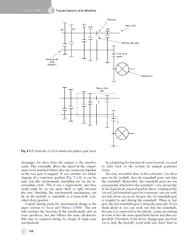
Fig. 5.1-7 Schematic of a front-wheel-drive gearbox gear layout.
disengages the drive from the engine) is the synchro- In considering the function of a synchromesh, we need
mesh. This essentially allows the speed of the compo- to refer back to the section on manual gearboxes
nents to be matched before they are connected together above.
as the new gear is engaged. If you consider the earlier You may remember that, in this schematic, the drive
diagram of a transverse gearbox (Fig. 5.1-6), it can be goes via the layshaft, then the mainshaft gears and onto
seen that the synchromesh assemblies are on the in- the mainshaft. Remember, the mainshaft gears are not
termediate shaft. This is not a requirement, and they permanently attached to the mainshaft – you can see this
could easily be on the input shaft or split between in the diagram of a manual gearbox above. Looking at the
the two. Similarly, the synchromesh mechanisms can 1st and 2nd mainshaft gears for a moment, you can work
be on the layshaft or mainshaft in a three-shaft, rear- out that when you are in 1st gear, the 1st mainshaft gear
wheel-drive gearbox. is coupled to and driving the mainshaft. When in 2nd
A good starting point for synchromesh design is the gear, the 2nd mainshaft gear is doing the same job. If you
paper written by Socin and Walters (1968). This not think about it, you can work out that the mainshaft,
only explains the function of the synchromesh used in because it is connected to the wheels, carries on rotating
many gearboxes, but also follows the main calculations at more or less the same speed both before and after any
that may be required during the design of single-cone gearshift. Therefore, if the driver changes gear, say from
synchromesh. 1st to 2nd, the layshaft, input shaft and clutch have to
116