
Page 122 - Automotive Engineering
P. 122
Transmissions and driveline CHAPTER 5.1
Mating face of gearbox – bolts to engine
5th gear in separate end case – 1st to 4th
gear in ‘maincase’ – 5 speed gearboxes Clutch
often developed from 4 speed units
operating
mechanism
Input shaft –
driven by clutch plate
Intermediate shaft
Synchromesh assemblies shown on Output from gearbox –
intermediate shaft – can also be on driveshafts connect
input shaft drive to road wheels –
driveshafts plug into
Output from gearbox – splines in differential
gears
driveshafts connect
drive to road wheels
Integral differential and final
drive gears – contained in
same gearbox casing as
main change gears
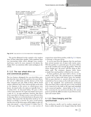
Fig. 5.1-6 Cross section of a front-wheel-drive manual gearbox.
The gearbox illustrated in this example is the simplest a typical rear-wheel-drive gearbox, while Fig. 5.1-9 shows
form of front-wheel-drive gearbox. Some gearboxes have a schematic of the gear layout.
two intermediate shafts, which, although more complex It can be seen from the diagrams that the gearboxes
(and hencetendtobe moreexpensive), do shortenthe have several separate sets of gears with various ratios.
design which can sometimes allow easier packaging in the With the gearbox in a particular gear, the power follows
vehicle. one of the possible paths through the gearbox. When the
driver changes gear, the power will flow along an alter-
native path. The schematic diagram below shows
5.1.3.2 The rear wheel drive car a simple four-speed gearbox to illustrate the concept.
and commercial gearbox In these gearboxes, the input shaft is driven, via the
clutch, by the engine. The constant gears are continually
Two key features distinguish the rear-wheel-drive gear- in mesh and the input shaft always drives the layshaft.
box from the front-wheel-drive gearbox discussed above; With no gear selected, i.e. neutral, all the gears on the
the lack of a differential, and the absence of the final mainshaft are free to rotate on the shaft and no drive can
drive reduction gear pair. Both of these will be found pass to the mainshaft. The synchromesh mechanism
within a different unit in the vehicle and this can be seen (discussed later) allows either the gears on the mainshaft
in the diagrams in the section on vehicle/power train to be connected to the shaft or the input and mainshaft
layout. As stated earlier, the ratios are typically from 4:1 to be connected together – shown below in Fig. 5.1-10.
to about 0.8:1. As discussed below, 4th gear is often This connection by the synchromesh allows the various
a direct drive between the input and output and so gives gears to provide the different ratios of speed between the
a ratio of 1:1. In some gearboxes, however, this direct input and output shafts.
drive is provided in 5th gear to give a more efficient drive
in that gear (there are no friction losses in the gear mesh
points). This means that the final drive needs to be ad- 5.1.3.3 Gearchanging and the
justed accordingly to provide the same overall gearing synchromesh
and the ratios in the lower gears will be higher to give the
same ratio spread – a ratio of around 5:1 rather than 4:1 The mechanism usually used in modern manual gear-
in first gear perhaps. Fig. 5.1-8 is a cross section of boxes to allow the gears to be changed (when the clutch
115