
Page 124 - Automotive Engineering
P. 124
Transmissions and driveline CHAPTER 5.1
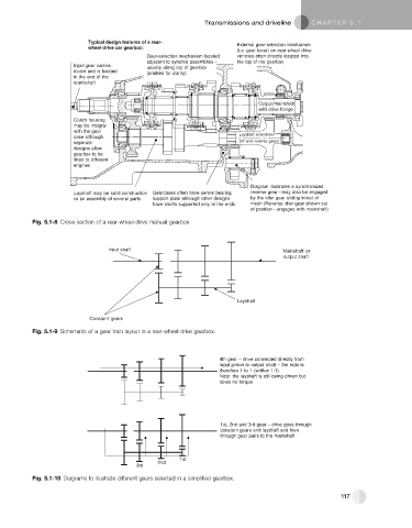
Typical design features of a rear- External gear-selection mechanism
wheel-drive car gearbox:
(i.e. gear lever) on rear wheel drive
Gear-selection mechanism located vehicles often directly located into
adjacent to synchro assemblies – the top of the gearbox
Input gear carries
usually along top of gearbox
clutch and is located (omitted for clarity)
in the end of the
crankshaft
Output/mainshaft
with drive flange
Clutch housing
may be integral
with the gear
case although Layshaft extension–
separate 5th and reverse gears
designs allow
gearbox to be
fitted to different
engines
Diagram illustrates a synchronized
Layshaft may be solid construction Gearcases often have centre bearing reverse gear – may also be engaged
or an assembly of several parts support plate although other designs by the idler gear sliding in/out of
have shafts supported only at the ends mesh (Reverse idler gear shown out
of position – engages with mainshaft)
Fig. 5.1-8 Cross section of a rear-wheel-drive manual gearbox.
Input shaft ‘Mainshaft’ or
output shaft
Layshaft
‘Constant’ gears
Fig. 5.1-9 Schematic of a gear train layout in a rear-wheel-drive gearbox.
4th gear – drive connected directly from
input pinion to output shaft – the ratio is
therefore 1 to 1 (written 1:1)
Note: the layshaft is still being driven but
takes no torque
1st, 2nd and 3rd gear – drive goes through
constant gears and layshaft and then
through gear pairs to the mainshaft
1st
2nd
3rd
Fig. 5.1-10 Diagrams to illustrate different gears selected in a simplified gearbox.
117