
Page 129 - Automotive Engineering
P. 129
CH AP TER 5 .1 Transmissions and driveline
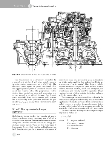
Fig. 5.1-16 Sectioned view of Jatco JF506E (courtesy of Jatco).
This transmission is electronically controlled by ratio (input speed for a given output speed and load) and
a control unit interfaced with other vehicle systems, an infinite ratio capability that makes them highly ap-
including engine management, via a CAN link. The propriate as a ‘starting device’. Their features include:
electronic control signals are passed to solenoid valves stepless variation in torque and speed without external
that apply hydraulic pressure to control clutches that control, vibration isolation, shock load absorption, low
select the required ratio. The programmed control maintenance and virtually wear-free operation. Disad-
strategy takes inputs from speed and temperature sen- vantages include efficiency, design limitations and great
sors to respond to the driver’s demand. This demand difficulty to control precisely.
comes principally from the accelerator pedal position The term torque converter is used here to describe the
but is modified by brake application and both the gear converter coupling as most frequently used in automotive
selector (D, 4, 3, 2) and a pattern selector (drive, sport applications.Thisisalso knownasaTrilokconverter.Itisso
and snow). called because, in a part of its operating range, it gives
a torque multiplication (behaving as a converter) andin the
remainder, it behaves as a coupling with a 1:1 torque ratio.
5.1.4.2 The hydrokinetic torque The basic equation defining the fluid torque acting on
converter impeller or turbine is:
2
Hydrokinetic drives involve the transfer of power T ¼ Cu D 5
through the ‘kinetic energy’ or velocity head of a fluid. In
such devices an impeller element creates the flow kinetic where T ¼ torque transferred
energy and a turbine element recovers the energy pro- C ¼ capacity constant
ducing a torque output. There are two main types of
u ¼ rotational speed
hydrokinetic devices: fluid coupling and fluid converter.
D ¼ diameter
Both these families provide an automatic adjustment of
122