
Page 132 - Automotive Engineering
P. 132
Transmissions and driveline CHAPTER 5.1
a reversal of torque on the reactor (since the three com- these three shafts locked to the gearbox casing or frame
ponent torques must still be in balance). In a converter leaving the remaining two to act as input and output
coupling, this cannot be reacted by the overrun clutch and shafts. Another alternative is for any two of the compo-
the reactor will free wheel. Above this speed ratio, the nents to be locked together and the whole unit rotates as
assembly behaves as a two-element device and operates as one, and although apparently trivial it is a convenient and
a fluid coupling. This gives the combined characteristic common option.
shown by the full line in Fig. 5.1-19 with increasing effi- An example of how the device works can be envisaged
ciency until the operating limits are reached as with a fluid with the carrier shaft locked, leaving the sun and annulus
coupling. free to rotate connected via the rotation of the planets
Further improvements in efficiency can be obtained if about their now fixed centres. The peripheral speed of
a lock-up clutch is used to mechanically lock the impeller any of the planet gears must be the same at both the
and casing to the turbine and hence directly connect contact radius of the sun and the radius of the annulus.
input and output shafts. This should only take place Thus, the number of gear teeth on each must determine
when the speed ratio is near unity, and needs to be con- the relative speed of the sun and annulus, and, since the
trolled gradually in order to prevent any driveline shock tooth pitch or module must be the same, their relative
that might be felt by the driver. This action can be ac- diameters. They will of course rotate in opposite di-
tuated hydraulically as required by the transmission rections. This ratio is referred to as the fundamental ratio
controller. i for the epicyclic gear and:
5.1.4.3 The epicyclic gear set – the key i ¼ u s ¼ t a ¼ D a
u a t s D s
component in the AT
where t is number of teeth and subscripts a and s refer to
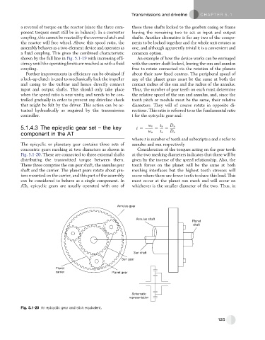
The epicyclic or planetary gear contains three sets of annulus and sun respectively
concentric gears meshing at two diameters as shown in Consideration of the torques acting on the gear teeth
Fig. 5.1-20. These are connected to three external shafts at the two meshing diameters indicates that these will be
distributing the transmitted torque between them. given by the inverse of the speed relationship. Also, the
These three comprise the sun gear shaft, the annulus gear tooth forces on the planet will be the same at both
shaft and the carrier. The planet gears rotate about pin- meshing interfaces but the highest tooth stresses will
ions mounted on the carrier, and this part of the assembly occur where there are fewer teeth to share this load. This
can be considered to behave as a single component. In must occur at the planet sun mesh and will occur on
ATs, epicyclic gears are usually operated with one of whichever is the smaller diameter of the two. Thus, in
Annulus gear
Annulus shaft
Planet
shaft
Sun shaft
Sun gear
Planet
carrier Planet gear
Schematic
representation
Fig. 5.1-20 An epicyclic gear and stick equivalent.
125