
Page 133 - Automotive Engineering
P. 133
CH AP TER 5 .1 Transmissions and driveline
sizing the gears for a required torque capacity, this mesh 5.1.4.4 JF 506E AT operation
region will indicate the limiting case.
Examination of the shaft speeds with other compo- The combined operation of these components can be seen
nents locked allows the derivation of the overall kine- by a more detailed examination of the JF 506E trans-
matic relation for an epicyclic set as: mission introduced above. Fig. 5.1-22 shows a schematic
representation of the transmission with different gears
u s ¼ð1 þ iÞu c iu a
selected. For clarity, the main components are only
There are limits in ratio that can be sensibly achieved with represented on one side of the shaft centreline, effectively
an epicyclic gear arising from a combination of physical half of the transmission. The main torque and hence
packaging, tooth and pinion strength and the need to have power flow path is shown by the heavy lines. There are
a whole number of teeth on all components. This gives two epicyclic gear sets on the primary shaft, labelled A and
values for the fundamental ratio generally in the range: B, and a further reduction epicyclic on the secondary
shaft.
2 i 4 In all gears the drive passes through the torque con-
verter to the primary shaft with the stator free wheel
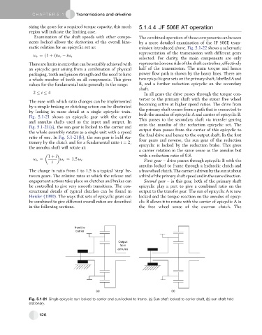
The ease with which ratio changes can be implemented
by a simple braking or clutching action can be illustrated becoming active at higher speed ratios. The drive from
by looking in more detail at a single epicyclic train. the primary shaft comes from a path that is connected to
Fig. 5.1-21 shows an epicyclic gear with the carrier both the annulus of epicyclic A and carrier of epicyclic B.
and annulus shafts used as the input and output. In This passes to the secondary shaft via transfer gearing
Fig. 5.1-21(a), the sun gear is locked to the carrier and onto the annulus of the reduction epicyclic set. The
the whole assembly rotates as a single unit with a speed output then passes from the carrier of this epicyclic to
ratio of one. In Fig. 5.1-21(b), the sun gear is held sta- the final drive and hence to the output shaft. In the first
tionery by the clutch and for a fundamental ratio i ¼ 2, four gears and reverse, the sun gear of the reduction
epicyclic is locked by the reduction brake. This gives
the annulus shaft will rotate at: a carrier rotation in the same sense as the annulus but
1 þ i with a reduction ratio of 0.8.
u a ¼ u c ¼ 1:5 u c First gear – drive passes through epicyclic B with the
i
annulus locked to frame through a hydraulic clutch and
The change in ratio from 1 to 1.5 is a typical ‘step’ be- a free wheel clutch. The carrier isdriven bythe sun atabout
tween gears. The relative rates at which the release and athirdoftheprimaryshaftspeedandinthesamedirection.
engagement actions take place on clutches and brakes can Second gear – in this gear, both of the primary shaft
be controlled to give very smooth transitions. The con- epicyclic play a part to give a combined ratio on the
structional details of typical clutches can be found in output to the transfer gear. The sun of epicyclic A is now
Heisler (1989). The ways that sets of epicyclic gears can locked and the torque reaction on the annulus of epicy-
be combined to give different overall ratios are described clic B allows it to rotate with the carrier of epicyclic A in
in the following sections. the free wheel sense of the overrun clutch. The
Input to
carrier
Output
from
annulus
(a) (b)
Fig. 5.1-21 Single epicyclic sun locked to carrier and sun locked to frame. (a) Sun shaft locked to carrier shaft, (b) sun shaft held
stationary.
126