
Page 131 - Automotive Engineering
P. 131
CH AP TER 5 .1 Transmissions and driveline
Fluid flow
Stator
Turbine Impeller
Fig. 5.1-18 Torque converter 3D with flow path.
The efficiency is: the converter-coupling operation described in the next
section.
power out T o u o
h ¼ ¼
power in T i u i 5.1.4.2c Torque converter
The blade angles of all three elements are curved to give The term torque converter is sometimes applied to the
the easiest flow path at a so-called ‘design point’. This basic fluid converter described above but it is used here to
point usually represents a peak efficiency with respect to describe the device that combines both converter and
speed ratio as shown in Fig. 5.1-19. At other conditions, coupling operation. This combination is typically used in
additional losses occur as flow meets the vanes at ‘awk- automotive applications and sometimes called a Trilok
ward’ angles, giving rise to shock losses. The blade cur- converter. The design is based closely on that of the fluid
vature means that the converter is not symmetrical and converter but with the addition of an overrun clutch
will not transmit torque effectively in the reverse sense (Heisler, 1989) connecting the reactor (stator) to its fixed
(negligible engine braking). There is a compromise in reference frame. This prevents the reactor from rotating
design between achieving a high torque ratio at stall (zero in one direction but will allow it to rotate freely in the
output speed) but at the expense of efficiency. It is other. Operation can be visualized during an acceleration
possible to achieve torque ratios of 5:1, but these days sequence with an increasing vehicle speed when the op-
fuel efficiency has become increasingly important and eration initially follows that of the fluid converter. The
automotive converters tend to operate around 2:1. reactor will be locked until a speed ratio is reached where
Fig. 5.1-19 also shows that beyond the point of max- the input and output torques are equal, and consequently
imum efficiency, the torque ratio tends below unity. This the reactor torque has reduced to zero. In converter
region is not attractive from an automotive viewpoint operation, any further increase in speed ratio above this
with reducing efficiency and hence the developments of would give a reduced torque ratio that can only occur by
100
Output to input torque ratio 1.0 40
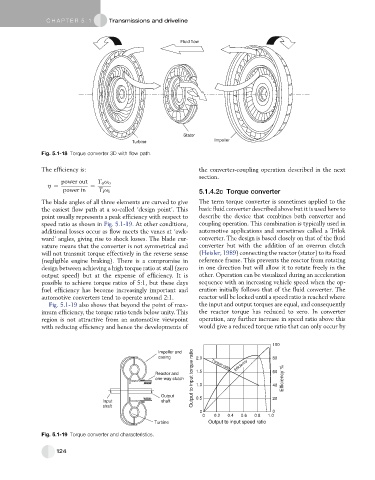
Impeller and
casing 2.0 Torque ratio 80
Reactor and 1.5 Efficiency 60
one-way clutch Efficiency %
Output 0.5 20
Input shaft
shaft
0 0
0 0.2 0.4 0.6 0.8 1.0
Turbine Output to input speed ratio
Fig. 5.1-19 Torque converter and characteristics.
124