
Page 130 - Automotive Engineering
P. 130
Transmissions and driveline CHAPTER 5.1
The capacity factor C, is independent on the detailed expressed either as a speed ratio (u o /u i ) or by a relative
geometry (blade angles, etc.), fluid density and viscosity slip s, defined by:
and, most importantly, it varies with speed ratio.
ðu i u o Þ u o
s ¼ ¼ 1
5.1.4.2a Fluid coupling u i u i
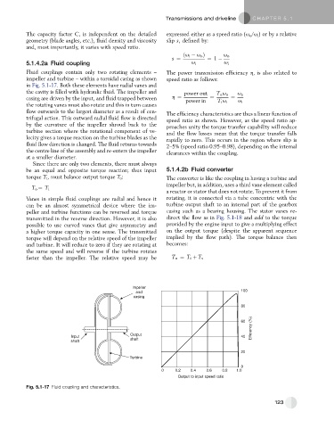
Fluid couplings contain only two rotating elements – The power transmission efficiency h, is also related to
impeller and turbine – within a toroidal casing as shown speed ratio as follows:
in Fig. 5.1-17. Both these elements have radial vanes and
the cavity is filled with hydraulic fluid. The impeller and power out T o u o u o
casing are driven by the input, and fluid trapped between h ¼ power in ¼ T i u i ¼ u i
the rotating vanes must also rotate and this in turn causes
flow outwards to the largest diameter as a result of cen- The efficiency characteristics are thus a linear function of
trifugal action. This outward radial fluid flow is directed speed ratio as shown. However, as the speed ratio ap-
by the curvature of the impeller shroud back to the proaches unity the torque transfer capability will reduce
turbine section where the rotational component of ve- and the flow losses mean that the torque transfer falls
locity gives a torque reaction on the turbine blades as the rapidly to zero. This occurs in the region where slip is
fluid flow direction is changed. The fluid returns towards 2–5% (speed ratio 0.95–0.98), depending on the internal
the centre line of the assembly and re-enters the impeller clearances within the coupling.
at a smaller diameter.
Since there are only two elements, there must always
be an equal and opposite torque reaction; thus input 5.1.4.2b Fluid converter
torque T i , must balance output torque T o : The converter is like the coupling in having a turbine and
impeller but, in addition, uses a third vane element called
T o ¼ T i
a reactor or stator that does not rotate. To prevent it from
Vanes in simple fluid couplings are radial and hence it rotating, it is connected via a tube concentric with the
can be an almost symmetrical device where the im- turbine output shaft to an internal part of the gearbox
peller and turbine functions can be reversed and torque casing such as a bearing housing. The stator vanes re-
transmitted in the reverse direction. However, it is also direct the flow as in Fig. 5.1-18 and add to the torque
possible to use curved vanes that give asymmetry and provided by the engine input to give a multiplying effect
a higher torque capacity in one sense. The transmitted on the output torque (despite the apparent sequence
torque will depend on the relative speed of the impeller implied by the flow path). The torque balance then
and turbine. It will reduce to zero if they are rotating at becomes:
the same speed and will reverse if the turbine rotates
faster than the impeller. The relative speed may be T o ¼ T i þ T s
Impeller
100
and
casing
80
Efficiency (%)
60
Output
Input 40
shaft shaft
20
Turbine
0
0 0.2 0.4 0.6 0.8 1.0
Output to input speed ratio
Fig. 5.1-17 Fluid coupling and characteristics.
123