
Page 43 - Automotive Engineering
P. 43
CH AP TER 2 .1 Measurement of torque, power, speed and fuel consumption
This whole subject, the coupling of engine and dyna- 2.1a.2.1 Overhung mass on engine
mometer, can give rise to more trouble than any other and dynamometer bearings
routine aspect of engine testing, and a clear un-
derstanding of the many factors involved is desirable. Care must be taken when designing and assembling
a shaft system that the loads imposed by the mass and
2.1a.2 The nature of the problem unbalanced forces do not exceed the overhung weight
limits of the engine bearing at one end and the dyna-
mometer at the other. Steel adaptor plates required to
The special feature of the problem is that it must be adapt the bolt holes of the shaft to the dynamometer
considered afresh each time an engine not previously flange or engine flywheel can increase the load on bear-
encountered is installed. It must also be recognized ings significantly and compromise the operation of the
that unsatisfactory torsional behaviour is associated system. Dynamometer manufacturers produce tables
with the whole system – engine, coupling shaft and showing the maximum permissible mass at a given dis-
dynamometer – rather than with the individual com- tance from the coupling face of their machines; the
ponents, all of which may be quite satisfactory in equivalent details for most engines is more difficult to
themselves. obtain, but the danger of overload should be kept in mind
Problems arise partly because the dynamometer is by all concerned.
seldom equivalent dynamically to the system driven by
the engine in service. This is particularly the case with
vehicle engines. In the case of a vehicle with rear axle 2.1a.3 Background reading
drive, the driveline consists of a clutch, which may itself
act as a torsional damper, followed by a gearbox, the The mathematics of the subject is complex and not
characteristics of which are low inertia and some readily accessible. Den Hartog gives what is possibly the
1
damping capacity. This is followed by a drive shaft and clearest exposition of fundamentals. Ker Wilson’s clas-
differential, itself having appreciable damping, two half sical treatment in five volumes is probably still the best
2
shafts and two wheels, both with substantial damping source of comprehensive information; his abbreviated
capacity and running at much slower speed than the version 3 is sufficient for most purposes. Mechanical
engine, thus reducing their effective inertia. Engineering Publications have published a useful practi-
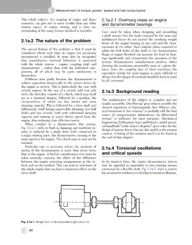
When coupled to a dynamometer this system, 4 5
Fig. 2.1a-1, with its built-in damping and moderate in- cal handbook while Lloyd’s Register gives rules for the
design of marine drives that are also useful in the present
ertia, is replaced by a single drive shaft connected to
a single rotating mass, the dynamometer, running at the context. A listing of the notation used is to be found at
same speed as the engine. The clutch may or may not be the end of this chapter.
retained.
Particular care is necessary where the moment of 2.1a.4 Torsional oscillations
inertia of the dynamometer is more than about twice
that of the engine. A further consideration that must be and critical speeds
taken seriously concerns the effect of the difference
between the engine mounting arrangements in the ve- In its simplest form, the engine–dynamometer system
hicle and on the testbed. This can lead to vibrations of may be regarded as equivalent to two rotating masses
the whole engine that can have a disastrous effect on the connected by a flexible shaft, Fig. 2.1a-2. Such a system
drive shaft. has an inherent tendency to develop torsional oscillations.
Fig. 2.1a-1 Simple form of dynamometer/engine drive line.
36