
Page 48 - Automotive Engineering
P. 48
Measurement of torque, power, speed and fuel consumption CHAPTER 2.1
The various stress levels for this steel are roughly as
follows: 200
ultimate tensile strength not less than 850 MPa
(55 t.s.i.)
0.1% proof stress in tension 550 MPa Alternating stress (MPa) 100
ultimate shear strength500 MPa
0.1% proof stress in shear 300 MPa
shear fatigue limit in 0
reversed stress 200 MPa 0 100 200 300 400 500
Mean shear stress (MPa)
It is clear that the permissible level of stress in the shaft
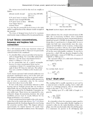
will be a small fraction of the ultimate tensile strength of Fig. 2.1a-6 Goodman diagram, steel shaft in shear.
the material.
The choice of designed stress level at the maximum
rated steady torque is influenced by two principal factors. shown indicates that, for a steady torsional stress of 200
MPa, the accompanying oscillatory stress (calculated
after taking into account any stress concentration factors)
2.1a.6 Stress concentrations, should not exceed 120 MPa. In the absence of detailed
keyways and keyless hub design data, it is good practice to design shafts for use in
engine test beds very conservatively, since the conse-
connection
quences of shaft failure can be so serious. A shear stress
calculated in accordance with eq. (9) of about 100 MPa
For a full treatment of the very important subject of for a steel with the properties listed should be safe under
stress concentration see Ref. 6. There are two particularly all but the most unfavourable conditions. To put this in
critical locations to be considered: perspective, a shaft 100 mm diameter designed on this
At a shoulder fillet, such as is provided at the junction basis would imply a torque of 19 600 Nm, or a power of
with an integral flange. For a ratio fillet radius/shaft 3100 kW at 1500 rev/min.
diameter ¼ 0.1 the stress concentration factor is The torsional stiffness of a solid shaft of diameter D
about 1.4, falling to 1.2 for r/d ¼ 0.2. and length L is given by:
At the semicircular end of a typical rectangular 4
keyway, the stress concentration factor reaches C s ¼ pD G (10a)
a maximum of about 2.5 nominal shear stress at an 32L
angle of about 50 from the shaft axis. The authors for a tubular shaft, bore d:
have seen a number of failures at this location and
angle. pðD d Þ
4
4
Cyclic stresses associated with torsional oscillations is an C s ¼ 32L (10b)
important consideration and as, even in the most care-
fully designed installation involving an internal combus-
tion engine, some torsional oscillation will be present, it is 2.1a.7 Shaft whirl
wise to select a conservative value for the nominal
(steady state) shear stress in the shaft. The coupling shaft is usually supported at each end by
In view of the stress concentration inherent in shaft a universal joint or flexible coupling. Such a shaft will
keyways and the backlash present that can develop in ‘whirl’ at a rotational speed N w (also at certain higher
2
2
splined hubs, the use of keyless hub connection systems speeds in the ratio 2 N w ,3 N w , etc.).
of the type produced by the Ringfeder Corporation are The whirling speed of a solid shaft of length L is
now widely used. These devices are supported by com- given by:
prehensive design documentation; however, the actual s ffiffiffiffiffiffiffiffiffiffiffiffi
installation process must be exactly followed for the 30p EpD 4
design performance to be ensured. N w ¼ L 2 64W s (11)
Stress concentration factors apply to the cyclic stresses
rather than to the steady state stresses. Fig. 2.1a-6 shows It is desirable to limit the maximum engine speed to
diagrammatically the Goodman diagram for a steel having about 0.8 N w . When using rubber flexible couplings it is
the properties specified above. This diagram indicates essential to allow for the radial flexibility of these cou-
approximately the relation between the steady shear plings, since this can drastically reduce the whirling speed.
stress and the permissible oscillatory stress. The example It is sometimes the practice to fit self-aligning rigid
41