
Page 51 - Automotive Engineering
P. 51
CH AP TER 2 .1 Measurement of torque, power, speed and fuel consumption
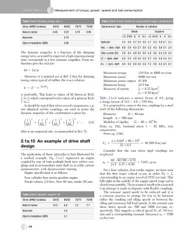
Table 2.1a-2 Damping energy ratio j Table 2.1a-4 Service factors for dynamometer/engine combinations
Shore (IHRD) hardness 50/55 60/65 70/75 75/80 Dynamometer type Number of cylinders
Natural rubber 0.45 0.52 0.70 0.90 Diesel Gasolene
Neoprene 0.79 1/2 3/4/5 6 8 10þ 1/2 3/4/5 6 8 10þ
Styrene-butadiene (SBR) 0.90 Hydraulic 4.5 4.0 3.7 3.3 3.0 3.7 3.3 3.0 2.7 2.4
Hyd. þ dyno. start 6.0 5.0 4.3 3.7 3.0 5.2 4.3 3.6 3.1 2.4
The dynamic magnifier is a function of the damping Eddy current (EC) 5.0 4.5 4.0 3.5 3.0 4.2 3.8 3.3 2.9 2.4
energy ratio: as would be expected a high damping energy
ratio corresponds to a low dynamic magnifier. Some au- EC þ dyno. start 6.5 5.5 4.5 4.0 3.0 5.7 4.8 3.8 3.4 2.4
thorities give the relation: d.c. þ dyno. start 8.0 6.5 5.0 4.0 3.0 7.2 5.8 4.3 3.4 2.4
M ¼ 2p=j
Maximum torque 110 Nm at 4000 rev/min
However, it is pointed out in Ref. 2 that for damping Maximum speed 6000 rev/min
energy ratios typical of rubber the exact relation: Maximum power output 65 kW
Maximum bmep 10.5 bar
j ¼ð1 e 2p=M Þ 2
Moments of inertia I e ¼ 0.25 kg m
I d ¼ 0.30 kg m 2
is preferable. This leads to values of M shown in Table
2.1a-3, which correspond to the values of j given in Table Table 2.1a-4 indicates a service factor of 4.8, giving
2.1a-2. a design torque of 110 4.8 ¼ 530 Nm.
It should be noted that when several components, e.g. It is proposed to connect the two couplings by a steel
two identical rubber couplings, are used in series the shaft of the following dimensions:
dynamic magnifier of the combination is given by: Diameter D ¼ 40 mm
2 2 2 2 Length L ¼ 500 mm
1 1 1 1 9
¼ þ þ þ (13) Modulus of rigidity G ¼ 80 10 Pa
M M 1 M 2 M 3
From eq. (9a), torsional stress s ¼ 42 MPa, very
conservative.
(this is an empirical rule, recommended in Ref. 5).
From eq. (10a)
4
2.1a.10 An example of drive shaft p 0:04 80 10 9
C s ¼ ¼ 40 200 N m=rad
design 32 0:5
Consider first the case when rigid couplings are
The application of these principles is best illustrated by employed:
a worked example. Fig. 2.1a-1 represents an engine r ffiffiffiffiffiffiffiffiffiffiffiffiffiffiffiffiffiffiffiffiffiffiffiffiffiffiffiffiffiffi
coupled by way of twin multiple-bush type rubber cou- n c ¼ 60 40 200 0:55 ¼ 5185 c:p:m:
plings and an intermediate steel shaft to an eddy current 2p 0:25 0:30
dynamometer, with dynamometer starting. For a four cylinder, four-stroke engine, we have seen
Engine specification is as follows: that the first major critical occurs at order N 0 ¼ 2,
Four cylinder four-stroke gasoline engine corresponding to an engine speed of 2592 rev/min. This
Swept volume 2.0 litre, bore 86 mm, stroke 86 mm falls right in the middle of the engine speed range and is
clearly unacceptable. This is atypical result tobe expected
if an attempt is made to dispense with flexible couplings.
The resonant speed needs to be reduced and it is
Table 2.1a-3 Dynamic magnifier M
a common practice to arrange for this to lie between
Shore (IHRD) hardness 50/55 60/65 70/75 75/80 either the cranking and idling speeds or between the
idling and minimum full load speeds. In the present case
Natural rubber 10.5 8.6 5.2 2.7
these latter speeds are 500 and 1000 rev/min, re-
Neoprene 4.0 spectively. This suggests a critical speed N c of 750 rev/
min and a corresponding resonant frequency n c ¼ 1500
Styrene-butadiene (SBR) 2.7
cycles/min.
44