
Page 50 - Automotive Engineering
P. 50
Measurement of torque, power, speed and fuel consumption CHAPTER 2.1
These differ in three important respects from those
of, say, a steel shaft in torsion:
1. The coupling does not obey Hooke’s law: the stiff-
ness or coupling rate C c ¼ DT/Dq increases with
torque. This is partly an inherent property of the
rubber and partly a consequence of the way it is
constrained.
2. The shape of the torque–deflection curve is not in-
dependent of frequency. Dynamic torsional charac-
Fig. 2.1a-8 Rubber bush type torsionally resilient coupling. teristics are usually given for a cyclic frequency of
10 Hz. If the load is applied slowly the stiffness is
found to be substantially less. The following values of
capacities of the various elements: the shaft, the cou- the ratio dynamic stiffness (at 10 Hz) to static stiff-
plings, the dynamometer and the engine itself. ness of natural rubber of varying hardness are taken
The couplings are the only element of the system, the from Ref. 4.
damping capacity of which may readily be changed, and
in many cases, for example with engines of automotive
size, the damping capacity of the remainder of the Shore ðIHRDÞ hardness 40 50 60 70
system may be neglected, at least in an elementary Dynamic stiffness
treatment of the problem, such as will be given here. Static stiffness 1:5 1:8 2:1 2:4
The dynamic magnifier M (Fig. 2.1a-3) has already
been mentioned as a measure of the susceptibility of the Since the value of C c varies with the deflection,
engine–dynamometer system to torsional oscillation. manufacturers usually quote a single figure which
Now referring to Fig. 2.1a-1, let us assume that there are corresponds to the slope of the tangent ab to the torque–
two identical flexible couplings, of stiffness C c , one at deflection curve at the rated torque, typically one third of
each end of the shaft, and that these are the only sources the maximum permitted torque.
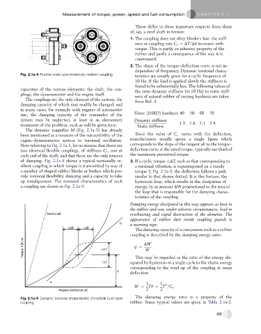
of damping. Fig. 2.1a-8 shows a typical torsionally re- 3. If a cyclic torque DT, such as that corresponding to
silient coupling in which torque is transmitted by way of a torsional vibration, is superimposed on a steady
a number of shaped rubber blocks or bushes which pro- torque T, Fig. 2.1a-9, the deflection follows a path
vide torsional flexibility, damping and a capacity to take similar to that shown dotted. It is this feature, the
up misalignment. The torsional characteristics of such hysteresis loop, which results in the dissipation of
a coupling are shown in Fig. 2.1a-9. energy, by an amount DW proportional to the area of
the loop that is responsible for the damping charac-
teristics of the coupling.
Damping energy dissipated in this way appears as heat in
the rubber and can, under adverse circumstances, lead to
Steel shaft overheating and rapid destruction of the elements. The
appearance of rubber dust inside coupling guards is
b a warning sign.
–Δθ +Δθ
The damping capacity of a component such as a rubber
coupling is described by the damping energy ratio:
Torque T (N m) +ΔT j ¼ DW
W
This may be regarded as the ratio of the energy dis-
–ΔT sipated by hysteresis in a single cycle to the elastic energy
corresponding to the wind-up of the coupling at mean
T deflection:
a
1 1
2
W ¼ Tq ¼ T =C c
Angular deflection ( ) 2 2
Fig. 2.1a-9 Dynamic torsional characteristic of multiple bush type The damping energy ratio is a property of the
coupling. rubber. Some typical values are given in Table 2.1a-2.
43