
Page 54 - Automotive Engineering
P. 54
Measurement of torque, power, speed and fuel consumption CHAPTER 2.1
10 9
Rubber bush coupling,
10 8 twin brushes joined by
swinging links
Dynamic torsional stiffness (Nm/rad) 10 6 Rubber bush coupling
7
10
Twin rigid universal
joints plus annular
5
10
type coupling as Fig. 2.1a-10
10
3
10 4
10 2
10 2 10 3 10 4 10 5 10 6 10 7
Torque capacity (Nm)
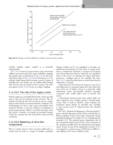
Fig. 2.1a-11 Ranges of torsional stiffness for different types of rubber coupling.
cylinder gasoline engine coupled to a hydraulic damage (which can be very puzzling) to bearings, un-
dynamometer. satisfactory performance of such items as torque trans-
Fig. 2.1a-11 shows the approximate range of torsional ducers, transmitted vibration to unexpected locations
stiffness associated with three types of flexible coupling: and serious drive line failures. Particular care should be
the annular type as illustrated in Fig. 2.1a-10, the mul- taken in the choice of couplings for torque shaft dyna-
tiple bush design of Fig. 2.1a-8 and a development of the mometers: couplings such as the multiple disc type,
multiple bush design which permits a greater degree of Fig. 2.1a-7, cannot be relied upon to centre these devices
misalignment and makes use of double-ended bushed sufficiently accurately.
links between the two halves of the coupling. The stiff- It has sometimes been found necessary to carry out in
ness figures of Fig. 2.1a-11 refer to a single coupling. situ balancing of a composite engine drive line where the
sum of the out of balance forces in a particular radial
relationship causes unacceptable vibration; specialist
2.1a.10.5 The role of the engine clutch
companies with mobile plant exist to provide this
service.
Vehicle engines are invariably fitted with a clutch and this
may or may not be retained on the test bed. The ad- Conventional universal joint type cardan shafts are
vantage of retaining the clutch is that it acts as a torque often required to run at higher speeds in test bed appli-
limiter under shock or torsional vibration conditions. The cations than is usual in vehicles; when ordering, the
disadvantages are that it may creep, particularly when maximum speed should be specified and, possibly,
torsional vibration is present, leading to ambiguities in a more precise level of balancing than the standard
power measurement, while it is usually necessary, when specified. 9
the clutch is retained, to provide an outboard bearing. BS 5265, Mechanical Balancing of Rotating Bodies,
Clutch disc springs may have limited life under test bed gives a valuable discussion of the subject and specifies 11
conditions. Balance Quality Grades. Drive line components should
generally be balanced to Grade G 6.3, or, for high speeds,
to grade G 2.5. The standard gives a logarithmic plot of
2.1a.10.6 Balancing of drive line the permissible displacement of the centre of gravity of
components the rotating assembly from the geometrical axis against
speed. To give an idea of the magnitudes involved, G 6.3
This is a matter which is often not taken sufficiently se- corresponds to a displacement of 0.06 mm at 1000 rev/
riously and can lead to a range of troubles, including min, falling to 0.01 mm at 5000 rev/min.
47