
Page 53 - Automotive Engineering
P. 53
CH AP TER 2 .1 Measurement of torque, power, speed and fuel consumption
There is no safe alternative, when confronted with an starting severe transient torques can arise. These have
engine of which the characteristics differ significantly from been known to result in the failure of flexible couplings of
any run previously on a given test bed, to following through apparently adequate torque capacity. The maximum
this design procedure. torque that can be necessary to get a green engine over
t.d.c. or that can be generated at first firing should be
2.1a.10.1 An alternative solution estimated and checked against maximum coupling
capacity.
The above worked example makes use of two multiple- Irregular running or imbalance between the powers
bush type rubber couplings with a solid intermediate generated by individual cylinders can give rise to exciting
shaft. An alternative is to make use of a conventional torque harmonics of lower order than expected in
propeller shaft with two universal joints, as used in road a multicylinder engine and should be borne in mind as
vehicles, with the addition of a coupling incorporating an a possible source of rough running. Finally, there is the
annular rubber element in shear to give the necessary possibility of momentary torque reversal when the
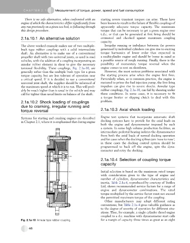
torsional flexibility. These couplings, Fig. 2.1a-10, are engine comes to rest on shutdown.
generally softer than the multiple bush type for a given However, the most serious problems associated with
torque capacity, but are less tolerant of operation near the starting process arise when the engine first fires.
a critical speed. If it is decided to use a conventional Particularly when, as is common practice, the engine is
universal joint shaft, the supplier should be informed of motored to prime the fuel injection pump, the first firing
the maximum speed at which it is to run. This will prob- impulses can give rise to severe shocks. Annular type
ably be much higher than is usual in the vehicle and may rubber couplings, Fig. 2.1a-10, can fail by shearing under
call for tighter than usual limits on balance of the shaft. these conditions. In some cases, it is necessary to fit
a torque limiter or slipping clutch to deal with this
2.1a.10.2 Shock loading of couplings problem.
due to cranking, irregular running and
torque reversal 2.1a.10.3 Axial shock loading
Systems for starting and cranking engines are described Engine test systems that incorporate automatic shaft
in Chapter 2.1, where it is emphasized that during engine docking systems have to provide for the axial loads on
both the engine and dynamometer imposed by such
a system. In some high volume production facilities, an
intermediate pedestal bearing isolates the dynamometer
from both the axial loads of normal docking operation
and for cases when the docking splines jam ‘nose to nose’;
in these cases the docking control system should be
programmed to back off the engine, spin the dyna-
mometer and retry the docking.
2.1a.10.4 Selection of coupling torque
capacity
Initial selection is based on the maximum rated torque
with consideration given to the type of engine and
number of cylinders, dynamometer characteristics and
inertia. Table 2.1a-4, reproduced by courtesy of Twiflex
Ltd, shows recommended service factors for a range of
engine and dynamometer combinations. The rated
torque multiplied by the service factor must not exceed
the permitted maximum torque of the coupling.
Other manufacturers may adopt different rating
conventions, but Table 2.1a-4 gives valuable guidance as
to the degree of severity of operation for different situ-
ations. Thus, for example, a single cylinder diesel engine
coupled to a d.c. machine with dynamometer start calls
Fig. 2.1a-10 Annular type rubber coupling. for a margin of capacity three times as great as an eight
46