
Page 171 - Autonomous Mobile Robots
P. 171
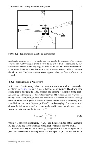
Landmarks and Triangulation in Navigation                  155


                                                          B 6


                                                                                 B 5
                                                         Mobile robot

                                       B 1
                                                                           B 4


                                                                  B 3
                                                    B 2


                              FIGURE 4.2 Landmarks and an onboard laser scanner.


                              landmarks is measured by a photo-detector inside the scanner. The scanner
                              outputs the relative angles (with respect to the robot frame) measured by the
                              scanner encoder at the falling edge of each landmark. The measurement vari-
                              ance would increase when the mobile robot moves around. This is because
                              the vibration of the laser scanner would appear when the floor surface is not
                              smooth.


                              4.3.2 Triangulation Algorithm
                              In the case of a stationary robot, the laser scanner senses all six landmarks,
                              as shown in Figure 4.3, from a single location continuously. Then these data
                              can be used to calculate the initial position and heading of the robot by the trian-
                              gulation algorithms proposed in References 8 and 15. There are two ways to do
                              triangulation. First, triangulation can be recursively implemented by choosing
                              three landmarks in Figure 4.3 in turn when the mobile robot is stationary. It is
                              actually identical to the “3-point problem” in land surveying. The laser scanner
                              detects the falling edges of three landmarks and in turn provides three angle
                              measurements, denoted by β i (i =1,2,3):


                                                   β i = tan −1  b yi − y l  − θ        (4.2)
                                                             b xi − x l

                              where θ is the robot orientation, (b xi , b yi ) are the coordinates of the landmark
                              β i , and (x l , y l ) are the coordinates of the laser scanner in a global frame.
                                 Based on the trigonometric identity, the equations for calculating the robot
                              position and orientation are easy to derive from Equation (4.2). More details can


                              © 2006 by Taylor & Francis Group, LLC


                                 FRANKL: “dk6033_c004” — 2006/3/31 — 16:42 — page 155 — #7