
Page 176 - Autonomous Mobile Robots
P. 176
160 Autonomous Mobile Robots
15
14.5
14
13.5 Odometry
EKF
13
E Desired
12.5
12
11.5
11
10.5
10.5 11 11.5 12 12.5 13 13.5 14 14.5 15
m
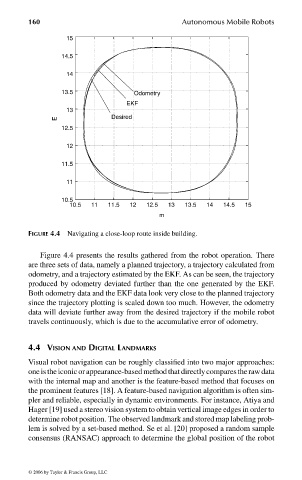
FIGURE 4.4 Navigating a close-loop route inside building.
Figure 4.4 presents the results gathered from the robot operation. There
are three sets of data, namely a planned trajectory, a trajectory calculated from
odometry, and a trajectory estimated by the EKF. As can be seen, the trajectory
produced by odometry deviated further than the one generated by the EKF.
Both odometry data and the EKF data look very close to the planned trajectory
since the trajectory plotting is scaled down too much. However, the odometry
data will deviate further away from the desired trajectory if the mobile robot
travels continuously, which is due to the accumulative error of odometry.
4.4 VISION AND DIGITAL LANDMARKS
Visual robot navigation can be roughly classified into two major approaches:
one isthe iconic orappearance-based method thatdirectly comparesthe raw data
with the internal map and another is the feature-based method that focuses on
the prominent features [18]. A feature-based navigation algorithm is often sim-
pler and reliable, especially in dynamic environments. For instance, Atiya and
Hager [19] used a stereo vision system to obtain vertical image edges in order to
determine robot position. The observed landmark and stored map labeling prob-
lem is solved by a set-based method. Se et al. [20] proposed a random sample
consensus (RANSAC) approach to determine the global position of the robot
© 2006 by Taylor & Francis Group, LLC
FRANKL: “dk6033_c004” — 2006/3/31 — 16:42 — page 160 — #12