
Page 36 - Autonomous Mobile Robots
P. 36
Visual Guidance for Autonomous Vehicles 19
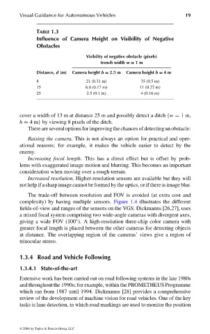
TABLE 1.3
Influence of Camera Height on Visibility of Negative
Obstacles
Visibility of negative obstacle (pixels)
trench width w = 1m
Distance, d (m) Camera height h = 2.5 m Camera height h = 4m
8 21 (0.31 m) 35 (0.5 m)
15 6.8 (0.17 m) 11 (0.27 m)
25 2.5 (0.1 m) 4 (0.16 m)
cover a width of 13 m at distance 25 m and possibly detect a ditch {w = 1m,
h = 4 m} by viewing 8 pixels of the ditch.
There are several options for improving the chances of detecting an obstacle:
Raising the camera. This is not always an option for practical and oper-
ational reasons; for example, it makes the vehicle easier to detect by the
enemy.
Increasing focal length. This has a direct effect but is offset by prob-
lems with exaggerated image motion and blurring. This becomes an important
consideration when moving over a rough terrain.
Increased resolution. Higher-resolution sensors are available but they will
not help if a sharp image cannot be formed by the optics, or if there is image blur.
The trade-off between resolution and FOV is avoided (at extra cost and
complexity) by having multiple sensors. Figure 1.4 illustrates the different
fields-of-view and ranges of the sensors on the VGS. Dickmanns [26,27], uses
a mixed focal system comprising two wide-angle cameras with divergent axes,
◦
giving a wide FOV (100 ). A high-resolution three-chip color camera with
greater focal length is placed between the other cameras for detecting objects
at distance. The overlapping region of the cameras’ views give a region of
trinocular stereo.
1.3.4 Road and Vehicle Following
1.3.4.1 State-of-the-art
Extensive work has been carried out on road following systems in the late 1980s
and throughout the 1990s; for example, within the PROMETHEUS Programme
which ran from 1987 until 1994. Dickmanns [28] provides a comprehensive
review of the development of machine vision for road vehicles. One of the key
tasks is lane detection, in which road markings are used to monitor the position
© 2006 by Taylor & Francis Group, LLC
FRANKL: “dk6033_c001” — 2006/3/31 — 16:42 — page 19 — #19