
Page 307 - Battery Reference Book
P. 307
2714 High-temperature thermally activated primary batteries
27.1.2 Configurations
Thermal batteries are manufactured in a wide
range of configurations to suit various types of
application. Some of the configurations available
from Catalyst Research Corporation are illustrated in
Figures 27.2-27.4.
Figure 27.2 shows the cell configuration of the cup
cell design. This was the first thermal battery design
used in production. The cup cell features a common
anode and two depolarizer pads, thereby doubling
the cell area. The eutectic lithium chloride-potassium
chloride electrolyte is impregnated on to glass tape to
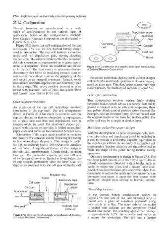
serve as a separator. These are solidified and die-cut Figure 27.3 Construction of a tungstic oxide open cell (Courtesy
to fit the cell. The heat source is zirconium-barium of Catalyst Research Corporation)
chromate, which forms an insulating ceramic mass on
combustion. A cathode lead on the periphery of the Potassium dichromate depolarizer is used in an open
cell serves as an intercell connector. Tungstic oxide cell, with lithium chloride-potassium chloride impreg-
and calcium chromate depolarizers are commonly used nated on glass tape. This depolarizer allows very high
in this design. The active positive material is often current density for fractions of seconds to about 5 s.
mixed with materials such as glass and quartz fibres
and formed paper-thin to fit the cell.
Pellet-type construction
This construction involves mixing finely divided
Open cellhape electrolyte
inorganic binder, which acts as a separator, with finely
An extension of the cup cell technology involved ground electrolyte eutectic salts and compacting them
elimination of the cup itself. The cell configuration into pellets. Finely ground positive active material (for
shown in Figure 27.3 has much in common with the example, calcium chromate) may be either mixed with
cup cell design, in that the electrolyte is impregnated the original binder or the basis for another pellet. The
on to glass tape and fibre pad depolarizers such as pellet cell may be a single or double layer.
tungstic oxide are used. The dumb-bell shaped part,
coated with calcium on one side, is folded around heat Multi-layer pelletsheat paper designs
paper discs and serves as the connector between cells.
Elimination of the cup is made possible by reducing With the development of pellet electrolyte cells, suffi-
the quantity of electrolyte and by restricting the battery cient electrolyte and depolarizer could be included in
to low or moderate dynamics. This design is useful a cell to provide a coulombic capacity equivalent to
the cup design without the necessity of a complex cell
for light to moderate loads (<50 mA/cm) for durations configuration. Binders added to the electrolyte tend to
of 1-1.5min. A significant feature of this design is retain the shape of the pellet during thermal battery
the thin cell, approximately 1.5 mm thick, including operations.
heat pad. The coulombic capacity per unit cell area One such configuration is shown in Figure 27.4. The
of the design is, however, limited to levels below that two-layer pellet consists of an electrolyte layer (lithium
of cup designs, particularly since the latter have two chloride-potassium chloride) with a binder such as
depolarizer pads and twice the cell area within the cell. kaolin or micro-size silica, and a second layer com-
posed of calcium chromate, plus some electrolyte. Cal-
cium metal is used as the anode and zirconium-barium
Insulator ring
chromate heat paper is again the heat source, with
dumb-bell shaped parts serving as intercell connec-
tions.
Glazed depolarizers
In the thermal battery configuration shown in
Figure 27.5, one side of one face of nickel strip is
coated with a glaze of vanadium pentoxide using
boric oxide as a flux. The other side of the nickel
/’
Heat pad Cathode lead is coated with calcium and the composite folded
(cell cup)
around heat paper. The resulting open-circuit voltage
Figure 27.2 Construction of a tungstic oxide closed cell (Courtesy is approximately 3.2V. An asbestos mat serves as
of Catalyst Research Corporation) a matrix for electrolyte. The cell has a square