
Page 313 - Battery Reference Book
P. 313
27/10 High-temperature thermally activated primary batteries
voltage of about 1.6V and can be worked at current of lithium-potassium chloride eutectic electrolyte and
densities up to several amps/cm-2 allowing thermal ceramic binder. The cathode is a mixture of iron pyrite
batteries to be discharged at very high currents and and electrolyte.
giving power densities at the 10-second or less rate The iron-based pyrotechnic is a pelletized wafer or
which are better than those obtained by another com- pill of iron powder and potassium perchlorate.
plete battery system weighing a few kg. For example, The anode assembly consists of an iron cup, which
a 6kg battery in a one-second discharge will have a is crimped around an elemental lithium carrier matrix.
specific power of 5 kWkg-' Here, a binding agent is used which binds the lithium
by surface tension in a manner similar to the 'gelling'
27.2.1 Production of batteries of electrolyte by ceramic binders. This anode has
numerous advantages when compared with lithium-
Mine Safety Appliances have designed a system with aluminium or lithium-silicon alloys for the bulk of
lithium as the active anode material and ferrous sul- thermal battery applications. These include greater
phide as the cathode, which shows significant improve- design versatility, higher power and energy densities,
ments in performance over the conventional systems. lower cost, excellent storage characteristics, higher
The Li-FeS2 system is based on a pile-type construc- current densities, very broad operational temperature
tion, which allows the battery voltage to be easily range and excellent safety characteristics.
adjusted by varying the number of series cells to meet Most experience has been with molten lithium anode
different application requirements. The components batteries where the lithium is mechanically retained.
making up the cells are the lithium, which is held in Figure 27.12 shows one version of a lithium-iron disul-
the anode assembly by a porous support material, the phide thermal battery cell. The design uses a heat
cathode (depolarizer layer), which is a thin disc of iron pellet, but heat paper versions are also feasible.
disulphide with a proportion of electrolyte, and an elec- Figure 27.13 shows the average service life of a 14-
trolyte layer, which is a disc of the electro!yte with a cell lithium-iron disulphide thermal battery designed
binder added to immobilize the electrolyte when it is in for power applications discharged at various constant-
the active molten state. The cells are interleaved with current loads to 24 V over a temperature range of -40
the heat source, also a disc of a pyrotechnic mixture to +71"C. This battery has 5.1 cm external diameter
of iron powder and potassium perchlorate. This com- and 4.4cm height and uses a modification of the cell
ponent is electrically conducting and acts as the series shown in Figure 27.12. For comparison, the perfor-
connection between the cells. The battery is activated mance of a similar-sized calcium-calcium chromate
by the igniter flame being transmitted via pyrotechnic thermal battery is also plotted. The lithium-iron disul-
fuse-strips to ignite the individual pyrotechnic discs. phide battery has a significantly higher capacity at the
The battery cell stack is thermally insulated and con- high power levels; at the lighter loads, the performance
tained in a mild steel case, hermetically closed by of both cells is limited by the cooling of the cell below
argon are welding. The electrical output is through the operating temperature.
terminals in glass-to-metal compression seals.
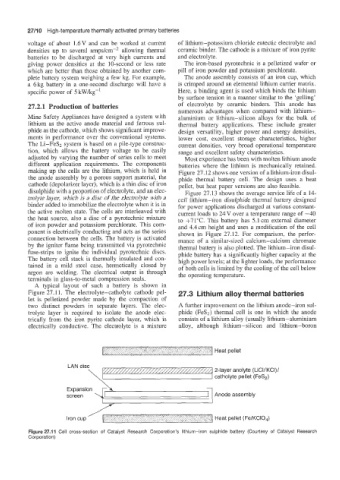
A typical layout of such a battery is shown in
Figure 27.11. The electrolyte-catholyte cathode pel- 27.3 Lithium alloy thermal batteries
let is pelletized powder made by the compaction of
two distinct powders in separate layers. The elec- A further improvement on the lithium anode-iron sul-
trolyte layer is required to isolate the anode elec- phide (FeS2) thermal cell is one in which the anode
trically from the iron pyrite cathode layer, which is consists of a lithium alloy (usually lithium- aluminium
electrically conductive. The electrolyte is a mixture alloy, although lithium-silicon and lithium-boron
1 1 Heat pellet
LAN disc
2-layer anolyte (LiCI/KCI)/
catholyte pellet (FeS,)
screen Anode assembly
Iron cup ' 1 Heat pellet (FelKClO,)
Figure 27.11 Cell cross-section of Catalyst Research Corporation's lithium-iron sulphide battery (Courtesy of Catalyst Research
Corporation)