
Page 488 - Battery Reference Book
P. 488
Transformerless charge circuits for nickel-cadmium batteries 47/21
Total resistance, Rt, may be determined by the turns
ratio and winding resistances (for the primary and
half of the secondary) given in the transformer design
data or by mea.surement of a sample. The measured
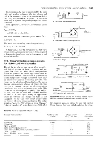
value may be adjusted for operating temperature where (a) Transformer and half-wave rectifier
warranted.
From Equation 47.10, the r.m.s. current in the centre
leg is R R
I,, = 0.707FIdC
Battery
Battery
= 0.707 x 1.8 x 1.2 = 1.53A
The series resistance power rating must handle Z2R or
(1.53)2(3.9 - Rt) (b) Transformer and full-wave bridge rectifier
The transformer secondary power is approximately
E,, x I,,, = 12 x 1.5 = 18 W
A better design may be provided by the full-wave Nickel-cadmium
bridge circuit. Although the number of diodes required battery
12
is doubled, the transformer may be less expensive and a.c
somewhat smaller.
/ -
ic) Reactance charger
47.8 Transformerless charge circuits
for nickel-cadmium batteries
Though the transformer-type circuit offers versatility D
and desired isolation of battery terminals and a.c.
power line there are other circuit configurations a.c. D
which are practical for special applications such as
experimental batteries. The division or proportioning
of the ‘charge source voltage and current values may (d) Resistance charger D-IN2069 silicon diode (or equivalent)
be obtained by reactive or resistive networks. The
former has the advantage of being heatless. The Union
Carbide reactance-type charger of Figure 47.19(c)
provides a constant current to nickel-cadmium +L Oneor
batteries of one to five series-connected cells. This 2 Eveready One deg %more
circuit has the advantages of simplicity, light weight, No. 960 cells __________ J 0 charging
no heat, and can be used with variable numbers le) Charging from primary batteries Dositions
of cells. It is used quite widely in applications
where the batteries and charger are built in and Figure 47.19 Charger circuits for Eveready sealed nickei-
inaccessible to the user. This circuit usually takes cadmium cells and batteries (Courtesy of Union Carbide)
the form of full-wave bridge rectification. The bridge
circuit in Figure 47.19(b) will deliver about 40dy F for suggested capacitor values for use with various
(value of capacitor, C) to the battery (see Table 47.5 Union Carbide Eveready nickel-cadmium batteries).
Table 47.5 Values for capacitor C in Figure 47.1 9(c)
Eveready batiely number Number of cells Charge current Nominal
in series (mA) (10h rate) capacitance
(PI
$20 or B20T 1 only 2 0.05
B50 or B50T 1-5 5 0.12
OB90 or OB90T 1-5 9 0.24
B150, B150T, CH150, CH15OT 1-5 15 0.37
B225, B225T, BH225, BH225T, CH225, CH225T 1-5 22.5 0.56
CH450, CH450T 1-5 45 1.12
BH500, BHSOOT, CH500, CH5OOT 1-5 50 1.25