
Page 486 - Battery Reference Book
P. 486
Transformer-type charger design (Union Carbide) for nickel-cadmium batteries 47/19
End-of-charge voltage at 10 h rate is estimated to be
1.45Vlcell and 2 x 1.45 = 2.90Edc.
Thus an a.c.1d.c. ratio of about 2 is needed. A stock
filament transformer with a secondary rating of 6.3 V,
0.6 A is selected (Stancor type P-6465 or equivalent).
Measurements of the open-circuit output voltage and
winding resistance give the following values.
With primary input voltage of 120 V a.c.,
Open-circuit secondary volts = 7.5V,.,.,
120
VP -
Turns ratio, N = - - - 16
=
v, 7.5
.--/ Voltage (d.c.) equatton factor Winding resistance (cold):
K
primary = 195 Q
' ~ " ~ " " ' ~ ' " " " ' 1
0 1 2 3 4 secondary = 1.3 Q
a.c./d.c. ratio
Total resistance (cold) referred to secondary:
Half-wave and full-wave centre tap:
a.c.1d.c. ratio = ___ (47.11)
E,,
Edc + nv,
Full-wave bridge: 195
=
= 1.3 + - 2.1 Q
a.c./d.c. ratio = E, E (47.12) 162
EdC + 2nV,
The hot resistance for a power transformer at rated
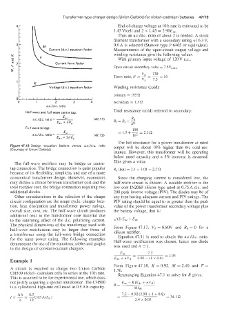
Figure 47.18 Design equation factors versus a.c./d.c. ratio output will be about 10% higher than the cold res-
(Courtesy of Union Carbide)
istance. However, this transformer will be operating
below rated capacity and a 5% increase is assumed.
The full-wave rectifiers may be bridge or centre- This gives a value
tap connection. The bridge connection is quite popular Rt (hot) = 2.1 x 1.05 = 2.2Q
because of its flexibility, simplicity and use of a more
economical transformer design. However, economics Since the charging current is considered low, the
may dictate a choice between transformer cost and the half-wave circuit is chosen. A suitable rectifier is the
total rectifier cost, the bridge connection requiring two low-cost IN2069 silicon type rated at 0.7SA d.c. and
additional diodes. 200 peak inverse voltage (PIV). The diodes may be of
Other considerations in the selection of the charge any type having adequate current and PIV ratings. The
circuit configuration are the usage cycle, charger loca- PIV rating should be equal to or greater than the peak
tion, heat dissipation and transformer power ratings, value of the power transformer secondary voltage plus
overall size, cost, etc. The half-wave circuit produces the battery voltage, that is:
additional neat in the transformer core material due
to the saturating effect of the d.c. polarizing current.
The physical dimensions of the transformer used with From Figure 47.17, Vd = 0.80V and Rd = 0 for a
haif-wave rectification may be larger than those of silicon rectifier.
a transformer using the full-wave bridge connection Equation 47.11 is used to obtain the a.c.1d.c. ratio.
for the same power rating. The following examples Half-wave rectification was chosen, hence one diode
demonstrate the use of the equations, tables and graphs was used and n = 1.
in the design af constant-current chargers.
Eac - 7.5
- = 2.03
Example 1 Edc + nvd 2.90 + (1 X 0.8)
From Figure 47.18, K = 0.92, M = 2.40 and F =
A circuit is required to charge two Union Carbide 1.76.
CH500 nickel-cadmium cells in series at the 10h rate. Rearranging Equation 47.1 to solve for R gives:
This is assumed to be for experimental use, which does
not justify acquiring a special transformer. The CHS00 Eac K(Edc + nvd)
is a cylindrical high-rate cell rated at 0.5 Ah capacity. R= MIdc
7.5 - 0.92 (2.90 + 1 x 0.8)
- = 34.1 Q
-
2.4 x 0.05