
Page 485 - Battery Reference Book
P. 485
47/18 Constant-current charging
the design equations of Figure 47.17 will be taken in
order for further definition. The value of Ed, or battery
voltage varies with state of charge, temperature, type
of nickel-cadmium cell construction and charge rate.
These variations are less significant to constant-current
operation than to other charge methods. The value
of Ed, for a fully charged nickel-cadmium battery I,, -
is between 1.35 and 1.4SVlcell for a 10h charge
rate at room temperature. However, 1.5 V/cell may (a) Half-wave
be used for charger design calculations. The charging
current, Idc, is chosen to fit the specific application.
The usage cycle, charge and discharge times of the
particular device dictate the charge rate. The 10h
rate is the highest recommended charge current for
the more common nickel-cadmium cells. To maintain
minimum charge current change with line voltage
variations, the ratio of E, to Edc should be as large ' rmr
as possible. This, however, results in relatively high (b) Full-wave bridge
power losses and heat dissipation in the series current-
limiting resistor. For practical reasons ratios of 1.5 to
2.5 are satisfactory, with the lower ratios being used
for full-wave rectification in applications above 1 A.
Equations 47.2,47.5 and 47.8 show that the value of
R is the sum of three separate resistances. The value
Rt, the resistance of the transformer, must be deter-
mined from manufacturers' specifications or by direct U I t AI
measurements of representative samples, and the value --+m D
of Rd may be found in the caption to Figure 47.17. (c) Full -wave centre tap Io rms
The value of the series limiting resistance, R,, must
be determined from the formulae in Figure 47.17. The (47.1)
purpose of Rt is to limit current. The value of R, is (47.2)
normally high compared with the other resistances in
the circuit, and in essence controls the current value (47.3)
since it constitutes the load on the power supply. The
power dissipation in R, varies as the square of r.m.s.
current flow. For calculating the wattage rating of R,, (47.4)
Equations 47.3, 47.6 and 47.10 give the relationship
between I,, and Idc. (47.5)
Typical values of rectifier forward threshold voltage, (47.6)
Vd, and rectifier dynamic resistance, Rd, for the design
equations of Figure 47.17 are given in the caption to
the figure. The current and peak inverse voltage rating
of the rectifier must be adequate for desired circuit
performance.
The equation factors K, M and F are functions of
the current conduction angle. Their values are based
on the ratio of E,,, the open-circuit r.m.s. voltage of
the transformer secondary, to the sum of the battery
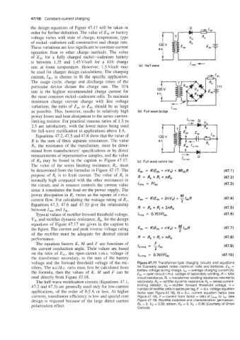
voltage and the forward threshold voltage of the rec- Figure 47.17 Transformer-type charging circuits and equations
tifiers. The a.c./d.c. ratio must first be calculated from for Eveready sealed nickel-cadmium cells and batteries. Edc =
the formula, then the values of K, M and F can be battery voltage during charge, /d, = average charging current (A),
E,, = open-circuit r.m.s. voltage of secondary winding, R = total
read directly from Figure 47.18. circuit resistance, Rt = transformer winding resistance referred to
The half-wave rectification circuits (Equations 47.1, secondary, Rd = rectifier dynamic resistance, R, = series current-
47.2 and 47.3) are generally used only for low-current limiting resistor, vd = rectifier forward threshold voltage, R =
number of rectifiercells in series per leg, K = d.c. voltageequation
applications, of the order of 0.SA or less. At higher factor (see Figure 47.18), M = d.c. current equation factor (see
currents, transformer efficiency is low and special core Figure 47.1 8), F = current from factor = ratio of I,,, to /dc (see
design is required because of the large direct current Figure 47.1 8). Rectifier materials and characteristics: germanium,
polarization effect. Rd = 0, vd = 0.35; silicon, Rd = 0, vd = 0.80 (Courtesy of Union
Carbide)