
Page 484 - Battery Reference Book
P. 484
Transformer-type charger des ;ign (Union Carbide) for nickel-cadmium batteries 47/17
R
Voltage compensation
*
\
(a) Alrernative 1
I
R
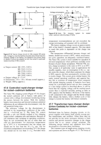
1 Figure 47.16 Varta TSL charging system for sealed
nickel-cadmium cells (Courtesy of Vartz)
temperature recommendations are not exceeded, the
charge terminating cell potential will be exhibited.
The battery tripping voltage occurs at approximately
80% of the battery's nominal capacity. The time taken
to reach this point is dependent on the charge rate
(b) Alternative 2 selected.
Figure 47.15 Typical charge circuits for Nife Jungner KR series The temperature differential between charger and
cells. Voltage V,, from the rectifier should be about three times the battery should not exceed &10"C, which necessitates,
charging voltage csf the battery; the resistance and power rating for cyclic operation, an adequately ventilated battery.
of resistor R should be adapted to limit the current to particular The Varta TSL system is most suitable for operation at
values (Courtesy of Nife Jungner)
elevated temperatures where problems normally occur
because of poor charge acceptance. With the TSL sys-
tem, charge acceptance is the same at 50°C as at 20°C.
e Output current: KR 15/51, 0.05 A. This system is of particular value in applications for
KR 23/43, 0.12 A. standby supplies, since an intemption in the a.c. sup-
KR 27/50, 0.20A. ply resets the charger, which then continues the charge
KR 35/62, 0.40A. to 80% capacity and then automatically switches over
KR 35/92, 0.60A. to trickle charge. This system gives similar battery life
e Output voltage: 0-17.4V. under normal operating conditions and superior bat-
0 Dimensions: 170 x 150 x 60mm overall (approx.). tery life at extremes of temperature when compared
0 Weight: 1600g (approx.). with normal charging systems. If batteries have been
stored for a prolonged period and are then connected
to a fast charge system as described above, it will be
47.6 Controlled rapid charger design found that the tripping voltage will be reached much
for nickel-cadmium batteries sooner than is expected (possibly putting as little as
20% capacity into the battery). However, if the battery
The Varta TSL charging system (Figure 47.16) charges is left connected to the charger and the trickle charge
the nickel-cadmium cell or battery with pulses of fully charges the battery, when a further cycle of fast
current with a voltage discriminator monitoring during charge is started the battery will behave normally.
the pauses between the pulses. With this method,
battery interconnection and internal resistance potential
differences do not influence the discriminator, only the 47.7 Transformer-type charger design
cell potential being seen. (Union Carbide) for nickel-cadmium
The reference voltage for the discriminator is batteries
matched to the temperature coefficient of the cells;
that is, -4mV/cell per "C. The Varta TSL system Published data for battery charging circuits. or d.c.
provides a safe and rcliable method of fast charging power supplies with battery load, usually assume per-
sealed nickel-cadmium cells and batteries. Because of fect transformers and rectifiers. Often these data do
cell tolerances and variations in operating conditions, not provide for the series resistance element to limit
Varta do not recommend the use of more than ten current and prevent excessive changes in the charge
cells per discriminator. For electrolyte temperatures current due to a.c. source voltage variations. The
up to 50°C it is recommended that the charge rate following design method and equations have been
should not be less than the 10 x Zl0 rate, and for developed to overcome these limitations.
electrollyte temperatures not exceeding 35°C the charge The common types of single-phase charging circuits
rate should not be less than 5 x Z~O. Provided these and equations are shown in Figure 47.17. The terms of