
Page 51 - Battery Reference Book
P. 51
1/36 Introduction to battery technology
lOOg to 960A at 2V (48 cells in parallel). It can be seen
go,& from Table 1.12 and Figures 1.14 and 1.15 that if, for
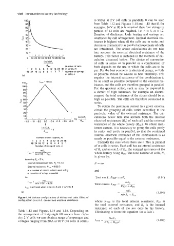
80 example, 24 V at 80 A is required then four strings in
70. parallel of 12 cells are required, i.e. n = 4, m = 12.
Duration of discharge, Joule heating and wattage are
unaffected by cell arrangement. Internal electrical res-
istance is highest when all the cells are in series and
decreases dramatically as parallel arrangements of cells
-
20 are introduced. The above calculations do not take
10 - into account the external electrical resistance of the
IIIIIIIIII battery. This factor is included in the methods of cal-
0 10 20 30 40 50 60 70 8090100 culation discussed below. The choice of connection
(mlnl I?,
of cells in series or in parallel or a combination of
Rem Number of cells both depends on the use to which the cells are to be
1 2 3 4 6 8 12 16 24 48 inseries,m put. For the best economy in electrical energy, as little
48 24 16 12 8 6 4 3 2 1 Nurnberof strings
of cells, n as possible should be wasted as heat internally. This
(al
requires the internal resistance of the combination to
=
105
A
Imax be as small as possible compared to the external res-
110
istance, and the cells are therefore grouped in parallel.
For the quickest action, such as may be required in
a circuit of high induction, for example an electro-
70 x X \ magnet, the total resistance of the circuit should be as
\
high as possible. The cells are therefore connected in
'y "\ series.
20 'y
"\
To obtain the maximum current in a given external
30
30
circuit the grouping of cells varies according to the
20
particular value of the external resistance. The cal-
10 x\ x log -
culations below take into account both the internal
(mln)R,
O ' I I I I I I
-1.5 -1.0 -0.5 0.0 f0.5 t1.0 +1.5 t2.0 electrical resistances (R,) of each cell and the external
t resistance of the whole battery (Rext). To obtain max-
(mln)R, imum current, it is necessary to group the cells partly
-= 1
R,,, in series and partly in parallel, so that the combined
internal electrical resistance of the combination is as
Number of cells in series, m nearly as possible equal to the external resistance.
12 3 4 6 812162448
4a241s12 a 8 4 3 2 1 Consider the case where there are n files in parallel
Number of strings of cells, n of m cells in series. Each cell has an internal resistance
of R, and an e.m.f. of E,, the external resistance of the
whole battery being kXt. The total number of cells, N,
is given by:
Assuming Ec = 2 V,
Internal resistance per cell, Rc - 0.1 N=nm
External resistance, RSxt = 0.05 S-2
rn = number of cells in series in each string and
n = number of strings in parallel
=
i.e. Total e.m.f., E~T mE, (1.91)
2m
IToT Total current, ITOT = mEc
mln X 0.1 + 0.05
I,, is achieved when m is 4 to 6 and n is 12 to 8 RTOT + Rext
(bl (1.101)
Figure 1.14 Various configurations of 48 two-volt cells. Effect of
configuration on emf., current and electrical resistance where Rm is the total internal resistance, Rex, is
the total external resistance, and R, is the internal
resistance of each of the mn cells in the battery.
Table 1.12 and Figures 1.14 and 1.15. Depending on Eliminating m from this equation (m = Nln),
the arrangement of forty-eight 80 ampere hour capa-
city 2-V cells we can obtain a range of amperages and NnE,
voltages ranging from 20 A at 96 V (48 cells in series) ITOT NR, + Rextn2 (1.102)
=