
Page 50 - Battery Reference Book
P. 50
Effect of cell layout in batteries on battery characteristics 1/35
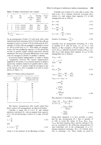
Table 1 .IO Battery characteristics: cells in parallel Consider next a series of in such cells in series. The
total e.m.f. (ET), internal electrical resistance (RT),
current (IT) and ampere hour capacity (67) of this
arrangement are as follows:
ET = mEc (1.91)
RT = mR, (1.92)
3 2 0.113 = 0.0330 60.0 28.4 120
6 2 0.116 = 0.0167 119.8 57.3 239.6
9 2 Ci.i/9 = 0.0111 180.2 86.2 360.4 (1.93)
'I: x RT x t , where t = 1 (1.95)
4.18
CT
h
for an arrangement of nine 2-V cells each with a total Duration of discharge = - (1.96)
internal electrical resistance of 0.1 R, if all the cells are mh
arranged in series a current of 20 A is delivered at 18 V, Consider now an arrangement consisting of n fifes
whereas if all the cells are arranged in parallel a current in parallel of m cells in series, i.e. an m x n cell
of l8OA is delivered at 2V. With either cell arrange- battery, in this example a 48-cell battery. The total
ments, the heat producing capacity is 9.56 cake11 per e.m.f. (ETOT), internal electrical resistance (RToT), cur-
second. In :general, higher currents and lower internal rent (ZTO~) and ampere hour capacity (eToT) of this
resistances but lower potential differences result when arrangement are as follows:
cells are arranged in parallel to produce a battery.
In practical battery arrangements, in order to obtain ETOT = WEc (1.91)
a compromise between the various characteristics I nxl
required in he battery, it is common practice to adopt a RTOT - mRc
layout that (combines batteries in parallel and in series.
Thus, a 48-cell 2-V battery might be arranged in any i.e.
of the layouts of n files in parallel of m cells in series m
shown in Table 1.11. RTOT = -R, (1.97)
Table 1.1 1 Practical battery arrangements (1.98)
Number of Number of batteries
m (n) in each series (m)
E
= mnh?
A 1 48 R,
B 2 24
m2hE,
C 3 16 -~
-
D 4 12 RTOT
E 6 8
F 8 6 - mhEToT (1.99)
-
G 12 4 RTOT
H 16 3 The duration of discharge (in hours) is
I 24 2
J 48 1
CTOT x RC - CTOT x RTOT
-
mxmxE, m2xE,
The batt'ery characteristics that would result from - CTOT x RTOT
these various cell arrangements are discussed below. - mETOT
Consider a single cell of enf. E, and internal
CTOT
electrical resistance R,, with an ampere hour capacity -~ (1. IQQ)
-
of G, Ah and producing a current of I, amps. For this mrTOT
cell, Using these equations it is now possible to calcu-
E,
IC = R, (1.93) late for any arrangement of n files in parallel of
m cells in series the values of ETOT, RTOT, ITOT,
and CTOT, the Joule heating effect and the wattage if val-
ues are assumed for the following characteristics of
(1.94) each individual cell in the arrangement: E, = 2V,
internal electrical resistance (R,) = 0.1 Wcell, dura-
where h is the duration of the discharge in hours. tion of discharge = 4 h. These results are given in