
Page 52 - Battery Reference Book
P. 52
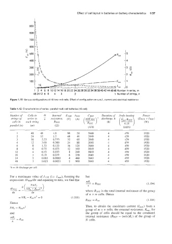
Effect of cell layout in batteries on battery characteristics   1/37
                     I
                     P
                  900


                     1  2  4  6  8  10 12 14 16 18 20 22 24 26 28 30 32 34 36 38 40 42 44 4648 Number in series,  m
                     482412  8  6   4   3    2                      1  Number of strings, n
       Figure 1.15 Various configurations of 48 two-volt cells. Effect of configuration on e.m.f., current and electrical resistance

       Table 1.12 Characteristics of series-parallel  multi-cell batteries (48-cell)

       Number  of   Cells in   m   Internal   ETOT  ITQT   CTOT   Duration oj  Joule heating   Power
                           -
       strings of   series in
        cells in   e8ach string   RTOT
       parallel  (n)   (m)       (a)                 (Ah)                (cays)
           1       48    48     4.8     96    20     3 840      4         459        1920
           2       24    12     1.2     48    40     3840       4         459        1920
           3       16    5.33   0.533    32   60     3840       4         459        1920
           4       12    3.00   0.300   24    80     3840       4         459        1920
           6        8     1.33   0.133   16   120    3840       4         459        1920
           8        6    0.75   0.075    12   160    3 840      4         459        1920
          12        4    0.33   0.033    8   240     3 840      4         459        1920
          16        3    0.19   0.019    6   320     3840       4         459        1920
          24        2    0.083   0.0083   4   480    3840       4         459        1920
          48        1    0.021   0.0021   2   960    3840       4         459        1920
       “h = 4 h discharge per cell


       For  a maximiam value  of ITOT (Le. I,,),   forming the   but
       expression: dlToT/dn and equating to zero, we find that
                                                                                       (1.104)
       &TOT  -  (NR, + Rextn2                      where RTOT is the total internal resistance of the group
            -
        dn         dn
                                                   of  n  x m cells. Hence
            = NR, - R,,trz2  = 0           (1.103)
                                                   RTOT = Rat                          (1 .l05)
       Hence
                                                   Thus,  to  obtain  the  maximum  current  (Im,)  from  a
       NR, = Rextn2
                                                   group of m x n  cells, the external resistance. R,,,,  for
       and                                         the  group  of  cells  should  be  equal  to  the  combined
                                                   internal  resistance  (RTOT = (rn/n)R,) of  the  group  of
                                                   N  cells.