
Page 190 - Bebop to The Boolean Boogie An Unconventional Guide to Electronics Fundamentals, Components, and Processes
P. 190
33
write-+'
- select
data_bus[15:0] v
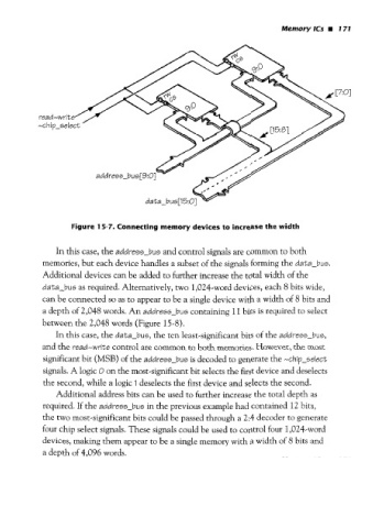
Figure 15-7. Connecting memory devices to increase the width
In this case, the address-bus and control signals are common to both
memories, but each device handles a subset of the signals forming the data-bus.
Additional devices can be added to further increase the total width of the
data-bus as required. Alternatively, two 1,024-word devices, each 8 bits wide,
can be connected so as to appear to be a single device with a width of 8
a depth of 2,048 words. An address-bus containing 11 bits is required to select
between the 2,048 words (Figure 15-8).
In this case, the data-bus, the ten least-significant bits of the address-bus,
and the read-write control are common to both memories. However, the most
significant bit (MSB) of the address-bus is decoded to generate the -chip-select
signals. A logic O on the most-significant bit selects the first device and deselects
the second, while a logic I deselects the first device and selects the second.
Additional address bits can be used to further increase the total depth as
required. If the address-bus in the previous example had contained 12 bits,
the two most-significant bits could be passed through a 2:4 decoder to generate
four chip select signals. These signals could be used to control four 1,024-word
devices, making them appear to be a single memory with a width of 8 bits and
a depth of 4,096 words.