
Page 200 - Bebop to The Boolean Boogie An Unconventional Guide to Electronics Fundamentals, Components, and Processes
P. 200
Programmable ICs 181
notation is applicable 1
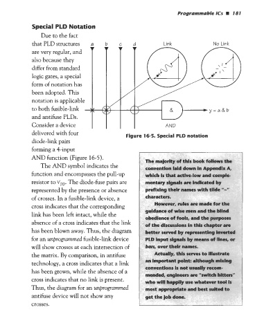
Special PLD Notation
Due to the fact
that PLD structures
are very regular, and
also because they
differ from standard
logic gates, a special
form of notation has
been adopted. This
to both fusible-link
and antifuse PLDs.
Consider adevice I I I I AND
-
delivered with four
Fiaure 16-5. Special PLD notation
diode-link pairs
forming a 4-input
AND function (Figure 16-5).
The majority of this book follows the
The AND symbol indicates the vention laid down in Appendix A,
function and encompasses the pull-up ich is that active-low and comple-
resistor to VDD. The diode-fuse pairs are ntary signats are indicated by
mes with tilde "-"
represented by the presence or absence
of crosses. In a fusible-link device, a
cross indicates that the corresponding
ance of wise men and the blind
link has been left intact, while the
absence of a cross indicates that the link the discussions in this chapter are
has been blown away. Thus, the diagram d by representing inverte
for an unprogrummed fusible-link device gnals by means of lines, or
will show crosses at each intersection of am, over their names.
the matrix. By comparison, in antifuse Actually, this serve
mportant point: although mixing
technology, a cross indicates that a link
onventions is not usually recom-
has been grown, while the absence of a
ded, engineers are "switch hitters"
cross indicates that no link is present. will happily use whatever tool is
Thus, the diagram for an unprogrammed riate and best suited to
antifuse device will not show any
crosses.