
Page 131 - 02. Subyek Computer Aided Design - Beginner’s Guide to SOLIDWORKS 2019- Level 1 by Alejandro Reyes
P. 131
Part Modeling
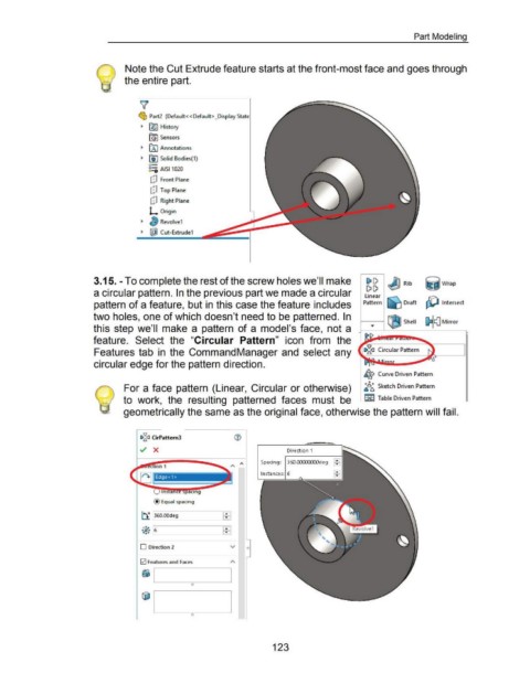
Note the Cut Extrude feature starts at the front-most face and goes through
the entire part.
~
~ Part2 (Defau lt<<Default> _Display '-t::oto:
~ (§)) History
[G) Sensors
~ [A) Annotations
~ 00 Solid Bodies(1)
o-
8:::0 AISI1020
C!J Front Plane
C!J Top Plane
cP Right Plane
L Origin
~ Revolve1
~ lf£iJ Cut-Extrude1
3.15.- To complete the rest of the screw holes we'll make ~ I) ~ Rib ~jwrap
I) I)
a circular pattern. In the previous part we made a circular linear
pattern of a feature, but in this case the feature includes Pattern ~ Draft ~ Intersect
two holes, one of which doesn't need to be patterned. In ~ Shell [) (]Mirror
this step we'll make a pattern of a model's face, not a
feature. Select the "Circular Pattern" icon from the
Features tab in the CommandManager and select any
circular edge for the pattern direction.
~ Curve Driven Pattern
0
For a face pattern (Linear, Circular or otherwise) ~{!);;, Sketch Driven Pattern
to work, the resulting patterned faces must be ~ Table Driven Pattern
geometrically the same as the original face, otherwise the pattern will fail.
c:§a CirPattern3
Direction 1
Spacing: 3ED.CO:XXXX:Odeg :
Instances: 6
@ Equal spacing
...
t± 360.00deg ...
...
~
• • 6 ...
••
D Direction 2 v
121 Features and Faces
~ 1....___----=-_ _____.
0
0
123