
Page 129 - 02. Subyek Computer Aided Design - Beginner’s Guide to SOLIDWORKS 2019- Level 1 by Alejandro Reyes
P. 129
Part Modeling
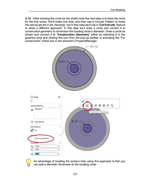
3.12. -After drawing the circle for the shaft's hole the next step is to draw the circle
for the first screw. We'll make one hole, and then use a Circular Pattern to make
the rest as we did in the 'Housing', but in this case we'll use a "Cut Extrude" feature
to show a different approach. In this step we'll draw a circle and convert it to
construction geometry to dimension the locating circle's diameter. Draw a circle as
shown and convert it to "Construction Geometry" either by selecting it in the
graphics area and clicking the icon from the pop-up toolbar or activating the "For
construction" check box in the element's PropertyManager.
,- (/J2.75J
0 Circle
Existing Relations
.h. Diameter3
Construction Geometry
Q) Fully Defined
Add Relations
0
D For const ruction
A
~ 1 o.ooo I ~
~ 1 o.ooo I ~
~ I I ~
An advantage of locating the screw's hole using this approach is that you
can add a diameter dimension to the locating circle.
121