
Page 158 - 02. Subyek Computer Aided Design - Beginner’s Guide to SOLIDWORKS 2019- Level 1 by Alejandro Reyes
P. 158
Beginner's Guide to SOLIDWORKS 2019- Level I
@ Hole Specification C?!®
../ X
[?j Type IT? Positions I
..
.. ... - -.--.--.-.. -.. -.. -.. -.. -... -.. -.. -.. --.--.--.--.--.-.. -.. -.. -.. -.. -.. -.. -.. --.-----------------------------------------.-. --...
. ~
.
/'
Favorite v . .
I
Hole Type
I
mmw I
[OJ mJ][I]
~rmrm
f)
Standard:
j ANSIInch ~
Type:
Screw Clearances
Hole Specifications
Size:
#6
I
I Normal I
.
D Show custom sizing .
---. -- --- --- --- --- --- --- --- --- --- --- --- --- -.--.--.--.------------------------------------------------------------------------ ..... -
End Condition
~ Through All
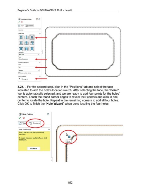
4.24. - For the second step, click in the "Positions" tab and select the face
indicated to add the hole's location sketch. After selecting the face, the "Point"
tool is automatically selected, and we are ready to add four points for the holes'
centers. Touch the round corner edges to reveal their centers and click in one
center to locate the hole. Repeat in the remaining corners to add all four holes.
Click OK to finish the "Hole Wizard" when done locating the four holes.
~ Hole Position
../ X
iJj Typ
Hole Position(s)
Select the face for t he hole or slot
position.
To create holes on multiple faces, click
3D Sketch.
[ 3D Sket ch J
0
152