
Page 207 - 02. Subyek Computer Aided Design - Beginner’s Guide to SOLIDWORKS 2019- Level 1 by Alejandro Reyes
P. 207
Beginner's Guide to SOLIDWORKS 2019- Level I
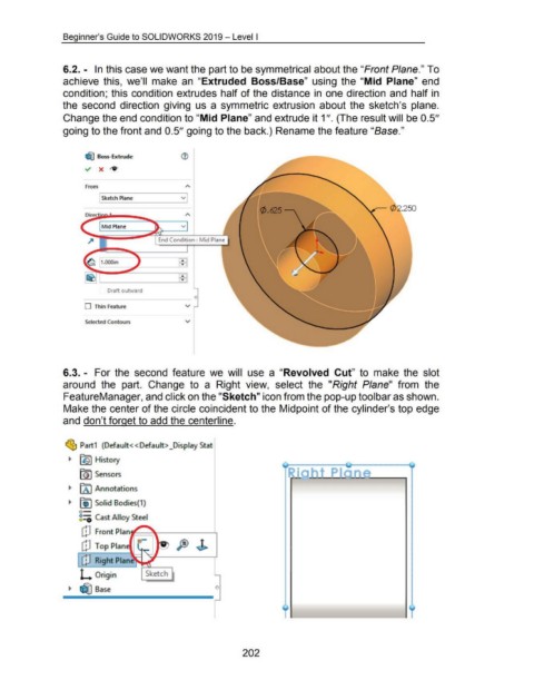
6.2. - In this case we want the part to be symmetrical about the "Front Plane." To
achieve this, we'll make an "Extruded Boss/Base" using the "Mid Plane" end
condition; this condition extrudes half of the distance in one direction and half in
the second direction giving us a symmetric extrusion about the sketch's plane.
Change the end condition to "Mid Plane" and extrude it 1 ". (The result will be 0.5"
going to the front and 0.5" going to the back.) Rename the feature "Base."
~ Boss-Extrude ®
~ X IV'
From
Sketch Plane v
~ 0 2.250
Dir
Mid Plane v
End Condition : M id Plane
fBI
Draft outward
c
0 Thin Feature v
Selected Contours v
6.3. - For the second feature we will use a "Revolved Cut" to make the slot
around the part. Change to a Right view, select the "Right Plane" from the
FeatureManager, and click on the "Sketch" icon from the pop-up tool bar as shown.
Make the center of the circle coincident to the Midpoint of the cylinder's top edge
and don't forget to add the centerline.
~ Part1 (Default<< Default> _Display Stat
~ ~~ History
tj) Sensors
~ [A I Annotations
~ ~ Solid Bodies(1)
o-
8::0 Cast Alloy Steel
[j] Front Plan '------".__ ___ _____.,
[j] Top Plan
C!] Right Plane ~
r-""----,
L Origin Sketch
~ ~ Base 0
202