
Page 218 - 02. Subyek Computer Aided Design - Beginner’s Guide to SOLIDWORKS 2019- Level 1 by Alejandro Reyes
P. 218
Part Modeling
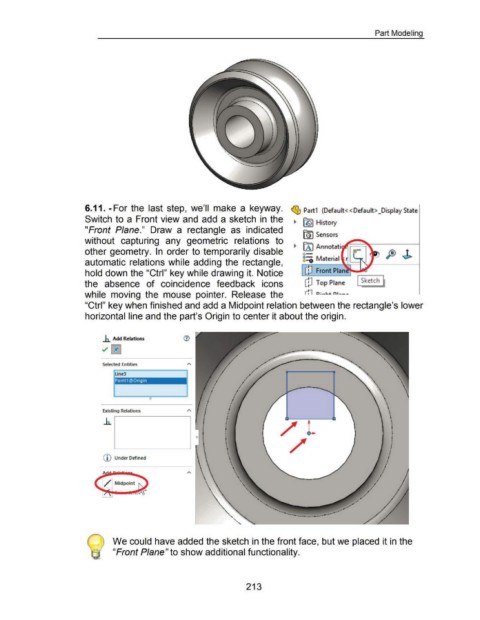
6.11. -For the last step, we'll make a keyway. ~ Part1 (Default< <Default> _Display State
Switch to a Front view and add a sketch in the ~ ~ History
"Front Plane." Draw a rectangle as indicated (Q) Sensors
without capturing any geometric relations to
~ [A I Annotati
other geometry. In order to temporarily disable o- PJ J>
automatic relations while adding the rectangle, 8::0 Material
hold down the "Ctrl" key while drawing it. Notice Front Plan
the absence of coincidence feedback icons cP Top Plane I Sketch j
while moving the mouse pointer. Release the rn o:-a..~ n•---
"Ctrl" key when finished and add a Midpoint relation between the rectangle's lower
horizontal line and the part's Origin to center it about the origin .
.h. Add Relations
~ 0
Selected Entities
line3
•
Pointl @Ongm I •
.. •
•
•
I
: •
0 •
Existing Relations
()
CD Under Defin ed
We could have added the sketch in the front face, but we placed it in the
"Front Plane" to show additional functionality.
213