
Page 231 - 02. Subyek Computer Aided Design - Beginner’s Guide to SOLIDWORKS 2019- Level 1 by Alejandro Reyes
P. 231
Part Modeling
For the 'Worm Gear Shaft' we will review the Revolved Feature previously
learned, the sketch Polygon tool, and a Mid Plane cut.
Revolve Hex cut
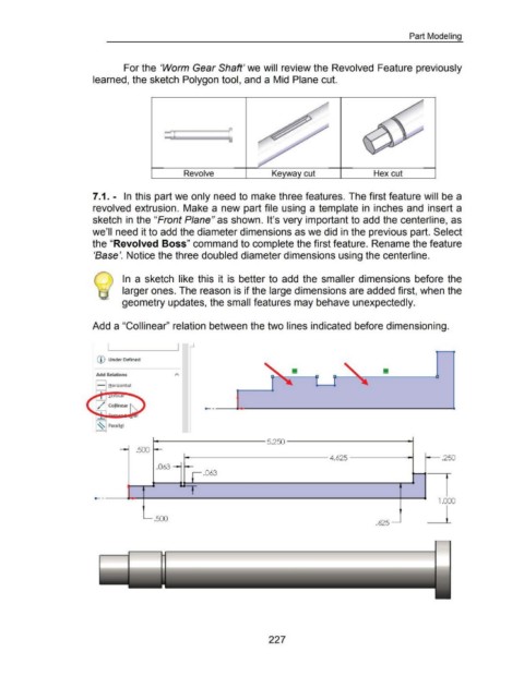
7 .1. - In this part we only need to make three features. The first feature will be a
revolved extrusion. Make a new part file using a template in inches and insert a
sketch in the "Front Plane" as shown. It's very important to add the centerline, as
we'll need it to add the diameter dimensions as we did in the previous part. Select
the "Revolved Boss" command to complete the first feature. Rename the feature
'Base'. Notice the three doubled diameter dimensions using the centerline.
In a sketch like this it is better to add the smaller dimensions before the
larger ones. The reason is if the large dimensions are added first, when the
geometry updates, the small features may behave unexpectedly.
Add a "Collinear" relation between the two lines indicated before dimensioning.
(D Under Defined
Add Relations
- Horizont al
~ Parall! l
- .500 I - 5.250 ,.25
- 4.625 0
.063 - r- .063
-- ~, 1.00 0
_j_
- .500
.625 -
227