
Page 233 - 02. Subyek Computer Aided Design - Beginner’s Guide to SOLIDWORKS 2019- Level 1 by Alejandro Reyes
P. 233
Part Modeling
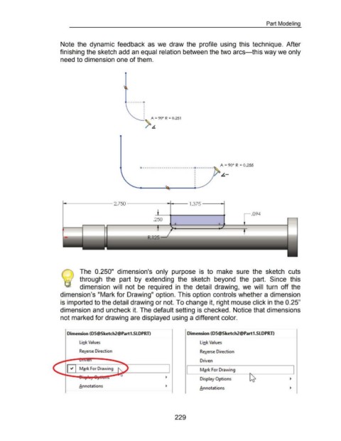
Note the dynamic feedback as we draw the profile using this technique. After
finishing the sketch add an equal relation between the two arcs-this way we only
need to dimension one of them .
. . . . . . . . ·+
'
'
'
'
'
'
'
: A = 90° R = 0.251
--.> .&.
A = 90° R = 0.255
+······················-··· ...... ·········
•
•
• 6-
•
•
•
•
•
•
.,_..__ ______ 2.750 _____ ____.., _ _ 1.375 -------t
.094
.250
The 0.250" dimension's only purpose is to make sure the sketch cuts
/ through the part by extending the sketch beyond the part. Since this
dimension will not be required in the detail drawing, we will turn off the
dimension's "Mark for Drawing" option. This option controls whether a dimension
is imported to the detail drawing or not. To change it, right mouse click in the 0.25"
dimension and uncheck it. The default setting is checked. Notice that dimensions
not marked for drawing are displayed using a different color.
Dimension (05@Sketch2@Part1.SLDPRTI Dimension (05@Sketch2@Part1.SLDPRTI
Link Values Link Values
Reverse Direction Reverse Direction
Driven
~ Mark For Drawing Mark For Drawing
~ ~
Display Options
Annotations
Annotations ~
229