
Page 440 - 02. Subyek Computer Aided Design - Beginner’s Guide to SOLIDWORKS 2019- Level 1 by Alejandro Reyes
P. 440
Detail Drawing
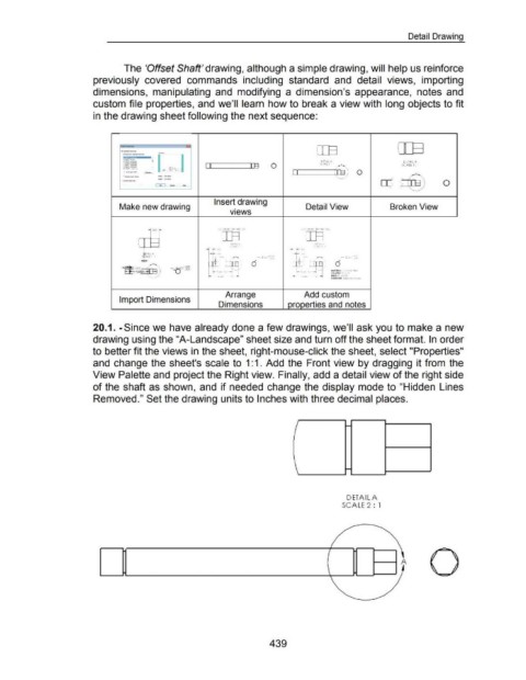
The 'Offset Shaft' drawing, although a simple drawing, will help us reinforce
previously covered commands including standard and detail views, importing
dimensions, manipulating and modifying a dimension's appearance, notes and
custom file properties, and we'll learn how to break a view with long objects to fit
in the drawing sheet following the next sequence:
-- Iii ern
·::=~- r 1 ITE
·--
·-- I I rn 0 SCALEl: l@ SCALE I: I
·--
DfTAlLA
I"""D,....,_
·--
DETAIL A
,..,..,,
,__ ..... ... l,._ ... ,,
·-~.,, r-~l - .m - I I 0
l(c-lll'm:- ...,. JJl_- ~
'
c::E:J L .... J( - II 0
'•
Insert drawing
Make new drawing Detail View Broken View
v1ews
- .500 ~ ~rn~ ~[§~
t-- DOAa.A onAJL A
lAlLA ·- ·-
$ Al[ 1:1 d i/J ..... - d 'll ..... -
-? i!r A , I 1-
~~ ·-:±I s.oov;,__r- MAI UIAt i"'tt,.,..,.Stlllotl
"'lf:~
.....
YotUM t :54¢V1"
DmciNU: ~0 ,..,es
WUOHI. sodlb
·~
Arrange Add custom
Import Dimensions
Dimensions properties and notes
20.1. -Since we have already done a few drawings, we'll ask you to make a new
drawing using the "A-Landscape" sheet size and turn off the sheet format. In order
to better fit the views in the sheet, right-mouse-click the sheet, select "Properties"
and change the sheet's scale to 1:1. Add the Front view by dragging it from the
View Palette and project the Right view. Finally, add a detail view of the right side
of the shaft as shown, and if needed change the display mode to "Hidden Lines
Removed." Set the drawing units to Inches with three decimal places.
-
-
DETAIL A
SCALE 2 : 1
1------1 A
439