
Page 496 - 02. Subyek Computer Aided Design - Beginner’s Guide to SOLIDWORKS 2019- Level 1 by Alejandro Reyes
P. 496
Assembly Modeling
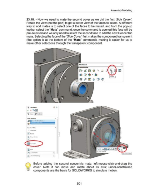
23.18. - Now we need to mate the second cover as we did the first 'Side Cover'.
Rotate the view (not the part) to get a better view of the faces to select. A different
way to add mates is to select one of the faces to be mated, and from the pop-up
tool bar select the "Mate" command; once the command is opened this face will be
pre-selected and we only need to select the second face to add the next Concentric
mate. Selecting the face of the 'Side Cover first makes the component transparent
(the option is at the bottom of the "Mate" command), making it easier for us to
make other selections through the transparent component.
v
I ~d~(j '\.® !
•
•
I
•
•
I ~ ~ ~ ~
• Mate
•
I
•
•
I ~ft>~~LB~
•
•
I
•
•
I
•
•
I
•
•
I
•
•
I
•
•
I ~ Concentric3
I" X "\0
~ Mates I <ffJ Analysis I
Mate Selections A "
~:~1 F"' <1>@S;d, Cm•-2
Face< 2> @Housing-1
Standard Mates
~ Coincident
~~~ Parallel ()
I I I Perpendicular
1©1 Concentric
~~~ lock
I HI .--l2.4-702-045-3in ____ __,.....,.: j
"ill
I ~ [177.noos603deg
Before adding the second concentric mate, left-mouse-click-and-drag the
cover. Note it can move and rotate about its axis; under-constrained
components are the basis for SOLIDWORKS to simulate motion.
501