
Page 491 - 02. Subyek Computer Aided Design - Beginner’s Guide to SOLIDWORKS 2019- Level 1 by Alejandro Reyes
P. 491
Assembly Modeling
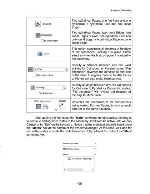
Two cylindrical Faces; one flat Face and one
~ Tangent cylindrical; a cylindrical Face and one linear
Edge.
Two cylindrical Faces, two round Edges, two
~~~ Concentr,jc' linear Edges or Axes, one cylindrical Face and
one round Edge, one cylindrical Face and one
D Lock rotation
linear Edge.
This option constrains all degrees of freedom
~ ~~ Lock of the component, locking it in place. Same
effect as when the first component is added to
the assembly.
Specify a distance between any two valid
entities for Coincident or Parallel mates. "Flip
l1• .. 111.oooin ____ ---=EE='I
dimension" reverses the direction to one side
D Flip dimension or the other. Using this mate on two flat Faces
or Planes will also make them parallel.
Specify an angle between any two flat entities
EEl
Ill I O.OOdeg for Coincident, Parallel, or Concentric mates.
"Flip dimension" will reverse the direction of
0 Flip dimension
the angular dimension.
~1ate alignment: ,,.____ Reverses the orientation of the components
~ ~ ~ being mated. For two Faces, to look at each
or other or in the same direction.
After adding the first mate, the "Mate" command remains active allowing us
to continue adding more mates to the assembly. It will remain active until we click
Cancel or hit "Esc" on the keyboard. Notice that the mate just added is listed under
the "Mates" box at the bottom of the PropertyManager. At this time, we'll add the
rest of the mates to locate the 'Side Cover' and fully define it. Do not exit the "Mate"
command yet.
Advanced Mates v
Mechanical Mates v
Mates
·······@ Concentric1 (Housing< 1 ~
< >
495