
Page 489 - 02. Subyek Computer Aided Design - Beginner’s Guide to SOLIDWORKS 2019- Level 1 by Alejandro Reyes
P. 489
Assembly Modeling
23.11. - Now that we have two components in the assembly, we are ready to add
mates (Relations) between the 'Housing' and the 'Side Cover'. Mates allow us to
reference one component to another,
2
;jS SOLIDWORKS File Edit View Insert Toe locating and restricting the motion
tb(§:l ~ ~C~ ~ between them. As explained earlier,
~ l?n~r components can be mated using their
Insert l!J2J
ComEpd~~er Compone Mate Co~~~~~nt Fa~~~~rs faCeS, planeS, edges, VertiCeS, axeS, and
sketch geometry. Click the "Mate" icon in
the Assembly tab or select the menu
)1
1-As_ s_em_ b-=-ly-L-La....;...yo_u_t ,__S_ke......,jt Mate · - • ~ ·-~~ · ~-
r "Insert, Mate" to locate the 'Side Cover'
in reference to the 'Housing'.
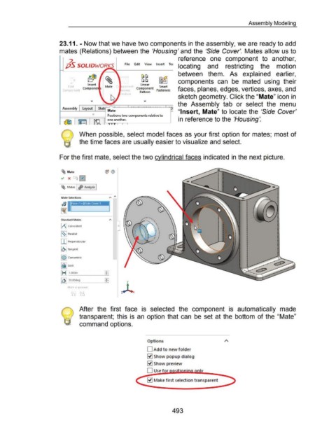
When possible, select model faces as your first option for mates; most of
the time faces are usually easier to visualize and select.
For the first mate, select the two cylindrical faces indicated in the next picture.
~ Mate (jJ <1)
~ X ts 0
~ Mates I ~ Analysis I
Mate Selections " ;..
~~~-----....11
Face<1>@Side Cover-1
Standard Mates
l/\1 Coincident 0
~~~ Parallel
I I I Perpendicular
IO.I Tangent
1©1 Concentric
l&llock
[8] r-~ .000- in ---""""'1[:j;==;l: I
[Q] ~O.OOdeg [:jl
Mate alignment:
After the first face is selected the component is automatically made
transparent; this is an option that can be set at the bottom of the "Mate"
command options.
Options
D Add to new folder
~ Show popup dialog
~ Show preview
D Use for
~ Make f irst selection transparent
493