
Page 516 - 02. Subyek Computer Aided Design - Beginner’s Guide to SOLIDWORKS 2019- Level 1 by Alejandro Reyes
P. 516
Assembly Modeling
After expanding the "Mates" folder in the FeatureManager we can see a
concentric mate and a coincident mate have been added. Selecting a mate
shows the part's mated faces in the graphics area.
1-t-_.J 1 ._ 1~1 1 \. I l U I 1'-
L Origin
~ ~ (f) Housing<1> (Machined< <Default> _Display State 1>)
~ ~ (-) Side Cover< 1 > (Machined<< Default> _Display State 1 >)
"" @@ Mates
@ Concentric1 (Housing< 1 >,Side Cover< 1 >)
1\ Coincident1 (Housing< 1 >,Side Cover< 1 >)
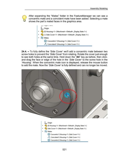
24.4. - To fully define the 'Side Cover' we'll add a concentric mate between two
screw holes to prevent the 'Side Cover from rotating. Rotate the cover just enough
to see both holes at the same time. Hold down the "Ait" key as before, then click-
and-drag the face or edge of the hole in the 'Side Cover to the screw hole in the
'Housing'. When the concentric mate icon is displayed, release the mouse button
to add the mate. Now the 'Side Cover is fully defined and can no longer be moved .
.
•
' •
' ' .......
--
L Origin
~ ~ (f) Housing<1> (Machined< <Default> _Display State 1>)
~ ~ Side Cover< 1 > (Machined<< Default> _Display State 1 >)
"" @@ Mates
@ Concentric1 (Housing< 1 >,Side Cover< 1 >)
/\ Coincident1 (Housing<1>,SideCover<1>)
@ Concentric2 (Housing< 1 >,Side Cover< 1 >)
521