
Page 518 - 02. Subyek Computer Aided Design - Beginner’s Guide to SOLIDWORKS 2019- Level 1 by Alejandro Reyes
P. 518
Assembly Modeling
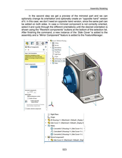
In the second step we get a preview of the mirrored part and we can
optionally change its orientation and optionally create an "opposite hand" version
of it. In this case, we don't need an opposite hand version, since the same part can
be added on both sides. In case a mirrored component is not correctly oriented,
select it and cycle through the different orientations until the desired orientation is
shown using the "Reorient components" buttons at the bottom of the selection list.
After finishing the command, a new instance of the 'Side Cover' is added to the
assembly and a "Mirror Component" feature is added to the FeatureManager.
0
1-----.---~-----r---- ..... ~ Assem3 (Default<Display ...
Lb all ~ R5'J History
'P ••
fWI Sensors
CJ~ Mirror Components ~ [A) Annotations
I u1 Front Plane I
ClJ Top Plane
Step 2: Set Orientation " "'
ClJ Right Plane
Verify the orientation of the
components to be mirrored and L Origin
adjust accordingly using the buttons ~ (!$ (f) Housing <1 > (Ma
below
Side Cover<1 >
Mates
Orient Components "
Side Cover-1
0
Reorient components
~ 3of 4 ~
Mirror type:
@ Bounding box center
0 Center of mass
.........
Create opposite .... ...... ~
hand version ••
Synchronize movement of flexible
subassembly components
D Isolate selected component
IJJ Right Plane
L Origin
~ ~ (f) Housing< 1 > (Machined<< Default> _Display ~
~ ~ Side Cover< 1 > (Machined<< Default> _Display 51
"' @@ Mates
@ Concentric1 (Housing< 1 >,Side Cover< 1 >) o
)\ Coincident1 (Housing< 1 >,Side Cover< 1 >)
@ Concentric2 (Housing< 1 >,Side Cover< 1 >)
"' GlliJ MirrorComponent1
~ ~ Side Cover<2> (Machined< <Default> _Displ
523