
Page 633 - 02. Subyek Computer Aided Design - Beginner’s Guide to SOLIDWORKS 2019- Level 1 by Alejandro Reyes
P. 633
Assembly and Design Table Drawings
Design Table Drawing
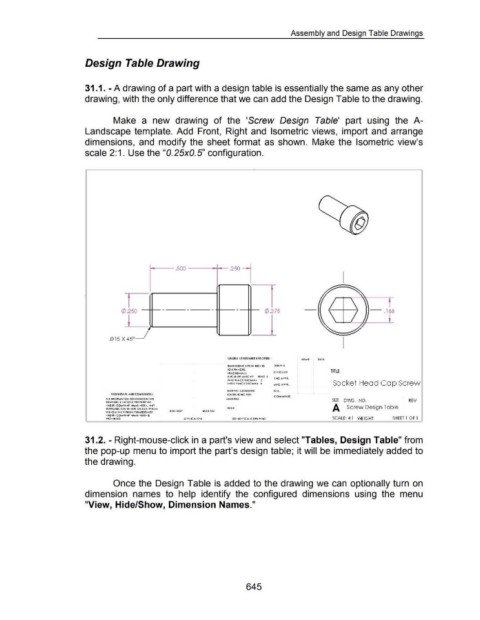
31.1. -A drawing of a part with a design table is essentially the same as any other
drawing, with the only difference that we can add the Design Table to the drawing.
Make a new drawing of the 'Screw Design Table' part using the A-
Landscape template. Add Front, Right and Isometric views, import and arrange
dimensions, and modify the sheet format as shown. Make the Isometric view's
scale 2:1. Use the "0.25x0.5" configuration .
. 2501
.500
I
c:t> .250 - - - - c:t> .3 75 - .188
l_
.015 X 45°
Ulle!S OTHERVvfiE SPECIFIEI> : ~AMI DAII
DMI>lSO>IS A'l 1>1 NC•IS D'A"' ~
1011 'A•ICIS:
C •IC ~ID TITLE :
A..C.I.JIA,:MAC M! lf~O l
tWO P1ACI DIC .... 1AI :!
1•,11 •lAC I DIC 1'.1A1 1 Socket Head Cop Screw
NIU•W CIOMIIU= CIA.
PROPIHTA I:Y A~D CO~Il Dill Til>. I I01UA>C~IC •n:
C Orf.., M I•~ IS:
, .. t N •OtMAt o·~ co•nAt•uo rf4 , .,.6 MAIItV....t SIZE DVVG. NO . REV
OM"' ~ICE 1•1 !0 II •10 •HI>' 0 I
<I•GU'I CO,..,PA•tr' ~· M(U>. A•~Y A Screw Design Table
U ''OD~C I 0>1 ~~ •t.fl OU<S A "'oO II
W I •OLIIIMI W 'llll•~ P(ft,,l!iSO...,OJ •II XI ASS>' ~SID 0>1
<I•GI'I CO....• 'A•fl"' ~·I M(U > 6
•10• 1111 D. SCALE: 4:1 \1\lEIGHT: SHEET! OFl
31.2. - Right-mouse-click in a part's view and select "Tables, Design Table" from
the pop-up menu to import the part's design table; it will be immediately added to
the drawing.
Once the Design Table is added to the drawing we can optionally turn on
dimension names to help identify the configured dimensions using the menu
"View, Hide/Show, Dimension Names."
645