
Page 628 - 02. Subyek Computer Aided Design - Beginner’s Guide to SOLIDWORKS 2019- Level 1 by Alejandro Reyes
P. 628
Assembly and Design Table Drawings
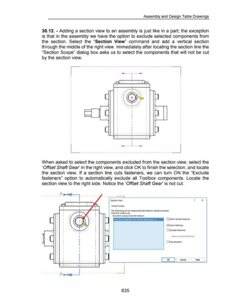
30.12. -Adding a section view to an assembly is just like in a part; the exception
is that in the assembly we have the option to exclude selected components from
the section. Select the "Section View" command and add a vertical section
through the middle of the right view. Immediately after locating the section line the
"Section Scope" dialog box asks us to select the components that will not be cut
by the section view.
~ ---------------------------------------------------------------------------------------------- ~
I • I • I
ri ll I I I ll_h
/
/ ' '
- ~~~ -
I (( I
- I I ~ (!> ~~~· ·po I I -
I "~
\ I I
~ ~
I - ~ - I
'-- I -
I I I
I
r -
I I
I I
I I
I
- I I -
I
- -
r' -- 1 -- l
-- --
.. I • _j
L ..............................................................................................
When asked to select the components excluded from the section view, select the
'Offset Shaft Gear in the right view, and click OK to finish the selection, and locate
the section view. If a section line cuts fasteners, we can turn ON the "Exclude
fasteners" option to automatically exclude all Toolbox components. Locate the
section view to the right side. Notice the 'Offset Shaft Gear is not cut.
A a ...
Section View ? X
- ~ -
Section Scope
The following list of components/rib features will be excluded
from the section cut:
Excluded components/rib features
I I Gear Box Complete< 20> /Offset Shaft Gear< 1 > D Don't cut all instances
I l I I
\ I2J Auto hatching
D Exclude fasteners
I Show excluded fasteners
I D Flip direction
I
I
I OK Cancel I [ Help J
_j
•
•
-- I --
·------------ A o.- -----· ----------------------------------
635