
Page 97 - 02. Subyek Computer Aided Design - Beginner’s Guide to SOLIDWORKS 2019- Level 1 by Alejandro Reyes
P. 97
Part Modeling
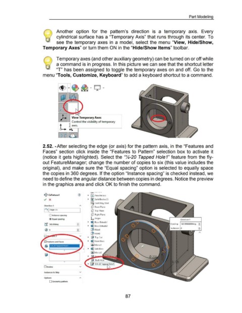
@) Another option for the pattern's direction is a temporary axis. Every
) cylindrical surface has a "Temporary Axis" that runs through its center. To
see the temporary axes in a model, select the menu "View, Hide/Show,
Temporary Axes" or turn them ON in the "Hide/Show Items" tool bar.
Temporary axes (and other auxiliary geometry) can be turned on or off while
a command is in progress. In this picture we can see that the shortcut letter
"T" has been assigned to toggle the temporary axes on and off. Go to the
menu "Tools, Customize, Keyboard" to add a keyboard shortcut to a command.
2.52. -After selecting the edge (or axis) for the pattern axis, in the "Features and
Faces" section click inside the "Features to Pattern" selection box to activate it
(notice it gets highlighted). Select the "~-20 Tapped Hole1" feature from the fly-
out FeatureManager; change the number of copies to six (this value includes the
original), and make sure the "Equal spacing" option is selected to equally space
the copies in 360 degrees. If the option "Instance spacing" is checked instead, we
need to define the angular distance between copies in degrees. Notice the preview
in the graphics area and click OK to finish the command.
' " ' - -··· - ·-
1>~<1 CirPattern1 ~ ~ fAI Annotations
../ X ~ I}J Solid Bodies(l)
o-
:=o Cast Alloy Steel
Direction 1
(!J Front Plane
It+ II Edge< 1> UJ Top Plane
UJ Right Plane
0 Instance spacing
@Equal spacing L Origin
~ ~ Boss-Extrudel
~I Spacing: 3ED.OC<XXXXX>deg ~
tf J360.00deg ~ ~ Boss-Extrude2
t;31 ~ Filletl
~ Fillet2
~ ll£jl Top Cut
~ ~ Front Boss
!ali!J Mirrorl
o ~ ~ Side Boss
0
!ali!J Mirror2
0
0Bod1es v
Instances to Skip v
O~OM A
0 Geometry pattern
87