
Page 233 - Biaxial Multiaxial Fatigue and Fracture
P. 233
Critical Plane-Energy Based Approach for Assessment of Biaxial Fatigue Damage where ... 217
(Nf<105) within a factor that varies from 1.2 to 2.0. A much better correlation of fatigue lives is
observed at high-cycle-fatigue regime (Nf>105), within a factor froml.O to 1.2.
DISCUSSION
Energy-critical plane parameters 11.5-171 including the parameter proposed in the present paper
are defined on specific planes and account for states of stress through combinations of the
normal and shear strain and stress ranges. These parameters depend upon the choice of the
critical plane and the stress and strain ranges acting on that plane.
For the proposed parameter, the critical plane is defined by the largest shear strain and stress
Mohr's circles during the reversals of a cycle, and the parameter consists of tensorial stress and
strain range components acting on this critical plane experiencing the maximum damage. The
total damage accumulation in a block loading history has been computed from the summation
of the normal and shear energies on the basis of a cycle-by-cycle analysis.
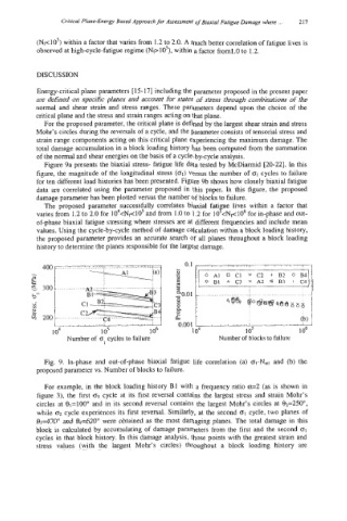
Figure 9a presents the biaxial stress- fatigue life data tested by McDiarmid [20-221. In this
figure, the magnitude of the longitudinal stress (01) versus the number of 61 cycles to failure
for ten different load histories has been presented. Figure 9b shows how closely biaxial fatigue
data are correlated using the parameter proposed in this paper. In this figure, the proposed
damage parameter has been plotted versus the number of blocks to failure.
The proposed parameter successfully correlates biaxial fati e lives within a factor that
g.
varies from 1.2 to 2.0 for 104<Nr<10s and from 1.0 to 1.2 for 10 <Nf<106 for in-phase and out-
of-phase biaxial fatigue stressing where stresses are at different frequencies and include mean
values. Using the cycle-by-cycle method of damage calculation within a block loading history,
the proposed parameter provides an accurate search of all planes throughout a block loading
history to determine the planes responsible for the largest damage.
- 400 c .. :...>...:..!.<.:.:.! .......... ...... .................... .... J s
3
L
j
----________(a) AI
Le
a
-
E 300 ......................
t3
UF
v)
2
j; 200 ............... (b) -
*
,
*
I
'
_._._d_L I 0.001 I
3
Fig. 9. In-phase and out-of-phase biaxial fatigue life correlation (a) ol-Nal and (b) the
proposed parameter vs. Number of blocks to failure.
For example, in the block loading history B1 with a frequency ratio 01=2 (as is shown in
figure 3), the first o1 cycle at its first reversal contains the largest stress and strain Mohr's
circles at €l1=10Oo and in its second reversal contains the largest Mohr's circles at 82=250",
while 02 cycle experiences its first reversal. Similarly, at the second 01 cycle, two planes of
83=470" and 84=620" were obtained as the most damaging planes. The total damage in this
block is calculated by accumulating of damage parameters from the first and the second 01
cycles in that block history. In this damage analysis, those points with the greatest strain and
stress values (with the largest Mohr's circles) throughout a block loading history are