
Page 488 - Biaxial Multiaxial Fatigue and Fracture
P. 488
472 JL.T SANTOS ETAL.
calculated as D/2. Since there is more than one longest chord, Deperrois approach faces
difficulty as explained in the above. For the above examples, Deperrois approach can be
applied since the projection onto any of the two longest chords gives identical results. The
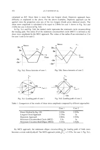
shear stress amplitude is calculated to be equal to 2.864~ for case 1 shown in Fig. 3(c) and
2.828~ for case 2 shown in Fig. 3(d).
In Fig. 3(c) and Fig. 3(d), the dashed circle represents the minimum circle circumscribing
the loading path. The radius R of the minimum circumscribed circle (MCC) is defined as the
shear stress amplitude by the MCC approach. The values of the radius R are calculated as 2.5~
for case 1 and 2a for case 2.
F
Time
Fig. 3(a). Stress histories of case 1. Fig. 3(b). Stress histories of case 2.
GXY
........ ......
...
OXXlJj
I I -2a
Fig. 3(c). Loading path of case 1. Fig. 3(d). Loading path of case 2.
Table 1. Comparison of the results of shear stress amplitude computed by different approaches
Case 1 Case 2
Direct Method by Eq. (10) 2.828a 2.828a
Longest Chord Approach 2.236a 2a
Deperrois Approach 2.864a 2.828a
Minimum Circumscribed Circle (MCC) 2.5a 2a
Minimum Circumscribed Ellipse (MCE) 3.535a 2.828a
By MCE approach, the minimum ellipse circumscribing the loading path of both cases
becomes a circle with R,=Rb=R. The MCE approach yields a = 3.53% for case 1, Fig. 3(c),