
Page 494 - Biaxial Multiaxial Fatigue and Fracture
P. 494
478 1L.I: SANTOS ETAL.
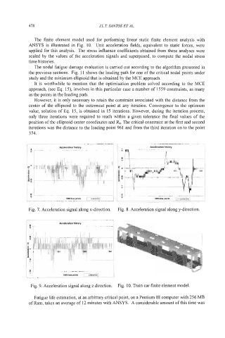
The finite element model used for performing linear static finite element analysis with
ANSYS is illustrated in Fig. 10. Unit acceleration fields, equivalent to static forces, were
applied for this analysis. The stress influence coefficients obtained from these analyses were
scaled by the values of the acceleration signals and superposed, to compute the nodal stress
time histories.
The nodal fatigue damage evaluation is carried out according to the algorithm presented in
the previous sections. Fig. 11 shows the loading path for one of the critical nodal points under
study and the minimum ellipsoid that is obtained by the MCE approach.
It is worthwhile to mention that the optimisation problem solved according to the MCE
approach, (see Eq. 15), involves in this particular case a number of 1559 constraints, as many
as the points in the loading path.
However, it is only necessary to retain the constraint associated with the distance from the
center of the ellipsoid to the outermost point at any iteration. Convergence to the optimum
value, solution of Eq. 15, is obtained in 15 iterations. However, during the iteration process,
only three iterations were required to reach within a given tolerance the final values of the
position of the ellipsoid center coordinates and %. The critical constraint at the first and second
iterations was the distance to the loading point 961 and from the third iteration on to the point
374.
Acceleration history
Fig. 7. Acceleration signal along x-direction. Fig. 8. Acceleration signal along y-direction.
I
Acceleration history
Fig. 9. -4cceleration signal along z direction. Fig. 10. Train car finite element model.
Fatigue life estimation, at an arbitrary critical point, on a Pentium I11 computer with 256 MB
of Ram, takes an average of 12 minutes with ANSYS. A considerable amount of this time was