
Page 79 - Biaxial Multiaxial Fatigue and Fracture
P. 79
64 N. ISOBE AND S. SAKURAI
Section JII, Division I, subsection NH [ 11 applies a factor of 2 as the FSRF for the fatigue life
assessment of weldments. This FSRF derived from the discussion for carbon and stainless
steels that show large inelastic deformation behavior at high temperature [2]. The suitable
assessment method for the fatigue life of the weldment of Ni-base superalloys, which use
higher temperature than stainless steels, has not been developed. Furthermore, such factors are
usually derived from uniaxial fatigue testing, while many real components are used under
complex multiaxial stress-strain conditions. It is, therefore, important to develop a life
assessment method that takes multiaxial stress or strain into account suitably. The assessment
of crack growth behavior is important in the life evaluation of components. This is because the
growth of cracks of the same size as grains is observed in the early stages of life and their
propagation dominates a component’s life [3].
In this study, we investigated the initiation and growth of micro-cracks in weldments of a
nickel-base superalloy, Hastelloy-X, under combined tensile and torsional loads at high
temperatures. The evaluation of the crack growth rates in weldments is discussed in order to
improve the life assessment of high-temperature components.
TEST PROCEDURE
A Ni-base superalloy, Hastelloy-X, and its weldment were tested. The weld metal was also
Hastelloy-X, but its content of trace elements, such as Si, Mn and W slightly differ from the
base metal. Their chemical compositions are listed in Table 1 and mechanical properties in
Table 2. Specimens were hollow cylinders 22 mm in diameter and 2 mm thick in the gauge
portion (Fig. 1). Welded specimens of two types were prepared: one was welded along the axial
direction, the other was along the direction of the circumferential direction, as shown in Fig.
l(b) and (c). Specimens were machined from blocks of welded two plates as shown in Fig. 2.
TIG welding was used and the weld was 7 mm wide. Figure 3 shows the microstructure of the
weldment. The average grain diameters were about 50 prn in the weld metal and about 20 pm
in the base metal.
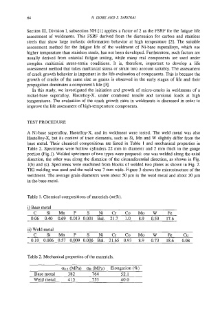
Table 1. Chemical compositions of materials (wt%).
i) Base metal
C Si Mn P S Ni Cr Co Mo W Fe
0.06 0.40 0.69 0.013 0.001 Bal. 21.7 1.0 8.9 0.50 17.6
ii) Weld metal
C Si Mn P S Ni Cr Co Mo W Fe Cu
0.10 0.006 0.57 0.009 0.006 Bal. 21.65 0.93 8.9 0.73 18.6 0.08
Table 2. Mechanical properties of the materials.
00.2 (MPa) OB (MPa) Elongation (%)
Base metal 382 764 52.1
Weld metal 415 753 40.0