
Page 81 - Biaxial Multiaxial Fatigue and Fracture
P. 81
66 N ISOBE AND S. SAKURAI
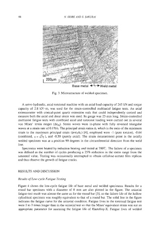
Base metal *Weld metal
Fig. 3. Microstructure of welded specimen.
A servo-hydraulic, axial-torsional machine with an axial load capacity of 245 kN and torque
capacity of 2.8 kN-m, was used for the strain-controlled multiaxial fatigue tests. An axial
extensometer with conical-point quartz extension rods that could independently control and
measure both the axial and shear strain was used. Its gauge was 25 mm long. Strain-controlled
multiaxial fatigue tests with combined axial and torsional loading were carried out in several
von Mises’ strain ranges (Ah). Strain waves were in-phase with fully reversed triangular
waves at a strain rate of O.l%/s. The principal strain ratios I$, which is the ratio of the minimum
strain to the maximum principal strain (@=&&I) [4], employed were -1 (pure torsion), -0.64
(combined, E = ,& ), and -0.50 (purely axial). The strain measurement point in the axially
welded specimen was at a position 90 degrees in the circumferential direction from the weld
line.
Specimens were heated by induction heating and tested at 700°C. The failure of a specimen
was defined as the number of cycles producing a 25% reduction in the stress range from the
saturated value. Testing was occasionally interrupted to obtain cellulose-acetate film replicas
and thus observe the growth of fatigue cracks.
RESULTS AND DISCUSSION
Results of Low-cycle Fatigue Testing
Figure 4 shows the low-cycle fatigue life of base metal and welded specimens. Results for a
round bar specimen with a diameter of 8 mm are also plotted in the figure. The uniaxial
fatigue-test result was almost the same as for the round bar [SI, so the failure life of the hollow
cylindrical specimen was roughly equivalent to that of a round bar. The solid line in the figure
indicates the fatigue curve for the uniaxial condition. Fatigue lives in the torsional fatigue test
were 2 to 3 times longer than in the uniaxial test so that the Mises’ equivalent strain was not an
appropriate parameter for assessing the fatigue life of Hastelloy-X. Fatigue lives of welded